Getting Results
RSLogix 5 Getting Results Guide
Important user information
Read this document and the documents listed in the additional resources section about installation, configuration, and operation of this equipment
before you install, configure, operate, or maintain this product. Users are required to familiarize themselves with installation and wiring instructions
in addition to requirements of all applicable codes, laws, and standards.
Activities including installation, adjustments, putting into service, use, assembly, disassembly, and maintenance are required to be carried out by
suitably trained personnel in accordance with applicable code of practice. If this equipment is used in a manner not specified by the manufacturer,
the protection provided by the equipment may be impaired.
In no event will Rockwell Automation, Inc. be responsible or liable for indirect or consequential damages resulting from the use or application of this
equipment.
The examples and diagrams in this manual are included solely for illustrative purposes. Because of the many variables and requirements associated
with any particular installation, Rockwell Automation, Inc. cannot assume responsibility or liability for actual use based on the examples and
diagrams.
No patent liability is assumed by Rockwell Automation, Inc. with respect to use of information, circuits, equipment, or software described in this
manual.
Reproduction of the contents of this manual, in whole or in part, without written permission of Rockwell Automation, Inc., is prohibited.
Throughout this manual, when necessary, we use notes to make you aware of safety considerations.
WARNING: Identifies information about practices or circumstances that can cause an explosion in a hazardous environment, which may lead to
personal injury or death, property damage, or economic loss.
ATTENTION: Identifies information about practices or circumstances that can lead to personal injury or death, property damage, or economic
loss. Attentions help you identify a hazard, avoid a hazard, and recognize the consequence
Important:
Identifies information that is critical for successful application and understanding of the product.
Labels may also be on or inside the equipment to provide specific precautions.
SHOCK HAZARD: Labels may be on or inside the equipment, for example, a drive or motor, to alert people that dangerous voltage may be
present.
BURN HAZARD: Labels may be on or inside the equipment, for example, a drive or motor, to alert people that surfaces may reach dangerous
temperatures.
ARC FLASH HAZARD: Labels may be on or inside the equipment, for example, a motor control center, to alert people to potential Arc Flash. Arc
Flash will cause severe injury or death. Wear proper Personal Protective Equipment (PPE). Follow ALL Regulatory requirements for safe work
practices and for Personal Protective Equipment (PPE).

Rockwell Automation Publication - LG5-GR002E-EN-P - December 2019 3
Table of contents
Purpose of this document .................................................................................................... 9
Intended audience ................................................................................................................. 9
Document conventions ........................................................................................................ 9
Online help ............................................................................................................................. 9
Training................................................................................................................................... 9
Commonly used terms ......................................................................................................... 9
Legal Notices ....................................................................................................................... 10
Chapter 1
System requirements .......................................................................................................... 13
Hardware requirements ............................................................................................ 13
Software requirements............................................................................................... 14
Activation ............................................................................................................................ 14
Installing RSLogix 5 software .......................................................................................... 15
Installing RSLinx Classic Lite software ................................................................. 15
Installing the FactoryTalk Services Platform ........................................................ 16
Installing the FactoryTalk Activation Client ....................................................... 17
Supported activation types for RSLogix 5 ..................................................... 18
Installing the Security Server Client ....................................................................... 18
Installing RSLogix 5 software .................................................................................. 19
Upgrading the FactoryTalk Platform ............................................................................ 24
Upgrading a Stand-Alone System on a Single Computer .................................. 24
Upgrading a Distributed FactoryTalk System on a Network ........................... 26
Upgrade FactoryTalk Services Platform on the Network Directory Server
Computer ............................................................................................................. 26
Add computer accounts to the Network Directory Server ........................ 27
Upgrade FactoryTalk Services Platform on the Remote Client
Computers ........................................................................................................... 27
Importing a Security Configuration from the Rockwell Software Security Server
into FactoryTalk Security ................................................................................................. 28
Configuring FactoryTalk Security for RSLogix 5........................................................ 30
Setting Security Policies for RSLogix 5 .................................................................. 32
Securing Actions for RSLogix 5............................................................................... 34
Setting security for actions globally................................................................. 38
Setting security for actions on a controller basis .......................................... 39
Starting RSLogix 5 software ............................................................................................. 40
Tr
oubleshooting installation ........................................................................................... 40
Preface
Installing and activating
RSLogix 5

Table of contents
4 Rockwell Automation Publication - LG5-GR002E-EN-P - December 2019
Chapter 2
Overview of RSLogix 5...................................................................................................... 43
Navigating RSLogix 5 ........................................................................................................ 43
Opening multiple program files .............................................................................. 45
Splitting the viewing window .......................................................................... 45
Opening multiple program windows ............................................................. 46
Quick Start steps for development ................................................................................. 46
Step 1 Configure a driver in RSLinx Classic ......................................................... 46
Step 2 Configure system communications ............................................................ 49
Step 3 Create a new project or open an existing project ..................................... 50
New Project ......................................................................................................... 50
Existing Project ................................................................................................... 51
Step 4 Add the chassis and I/O ............................................................................... 51
Step 5 Create program and data table files ............................................................ 52
Step 6 Enter a logic program .................................................................................... 53
Step 7 Add documentation to your logic instructions ........................................ 54
Step 8 Verify the program logic ............................................................................... 55
Step 9 Configure the communication channels ................................................... 55
Step 10 Download and go online ............................................................................ 56
Step 11 Monitor data files ........................................................................................ 56
Step 12 Search and replace instructions ................................................................. 57
Step 13 Print a report ................................................................................................ 58
Quick Start steps for maintenance .................................................................................. 59
Step 1 Establish communications with the processor ......................................... 59
Step 2 Go online ......................................................................................................... 59
Chapter 3
Opening a Project File ....................................................................................................... 61
Special Considerations ...................................................................................................... 61
Retrieve the PLC-5 A.I. Series documentation database ................................... 61
Open a 6200 Series PLC-5 Project ......................................................................... 62
Chapter 4
The chassis table ................................................................................................................. 63
Adding and configuring a chassis .................................................................................... 63
C
onfiguring a PLC or I/O adapter................................................................................. 64
Adding I/O modules ......................................................................................................... 65
Configuring I/O ................................................................................................................. 67
Getting started with RSLogix
5
Opening A.I. and 6200 project
files in RSLogix 5
Hardware configuration

Table of contents
Rockwell Automation Publication - LG5-GR002E-EN-P - December 2019 5
Chapter 5
Import database .................................................................................................................. 69
PLC-5 A.I. Series project documentation database ............................................. 69
6200 Series PLC-5 project documentation database .......................................... 70
RSLogix 5 documentation database ....................................................................... 70
CSV (Comma Separated Values) file ..................................................................... 71
ASCII delimited text file........................................................................................... 71
Export database ................................................................................................................... 72
RSLogix 5 ASCII delimited text file examples ..................................................... 73
Address symbols and descriptions (.EAS files) ............................................. 73
Page title and rung descriptions (.ERP files) ................................................. 73
Instruction comments (.EIC files) .................................................................. 73
Symbol groups (.ESG files) ............................................................................... 74
A.I. ASCII delimited text file examples ................................................................. 74
Address symbols and descriptions (.EAS files) ............................................. 74
Page title and rung descriptions (.ERP files) ................................................. 74
AB 6200 ASCII delimited text file ......................................................................... 74
Key Words ........................................................................................................... 75
CSV (Comma Separated Values) format .............................................................. 75
Chapter 6
Backing up your work ........................................................................................................ 77
Crash recovery ............................................................................................................. 78
Shortcuts for ladder editing .............................................................................................. 78
Quick Key Mapping .................................................................................................. 78
ASCII editing .............................................................................................................. 79
Example ASCII rung ......................................................................................... 80
Dot commands ........................................................................................................... 80
Other shortcuts and tips ........................................................................................... 81
Selecting multiple rungs .................................................................................... 81
Jumping to a rung ............................................................................................... 81
Keyboard shortcuts ............................................................................................ 81
Addressing ........................................................................................................................... 81
Branching .
............................................................................................................................ 82
Add a branch ............................................................................................................... 82
Move a branch ............................................................................................................. 82
Expand a branch ......................................................................................................... 82
Nested branches .......................................................................................................... 82
Parallel branches ......................................................................................................... 82
Copy branch leg .......................................................................................................... 82
Copy entire branch structure ................................................................................... 82
Delete a branch ........................................................................................................... 82
Undo operation .................................................................................................................. 82
Online editing ..................................................................................................................... 83
Importing or exporting the
documentation database
More about entering ladder
logic

Table of contents
6 Rockwell Automation Publication - LG5-GR002E-EN-P - December 2019
Lower-case zone markers .......................................................................................... 83
Upper-case zone markers .......................................................................................... 84
Online editing example ............................................................................................. 84
Online editing restrictions........................................................................................ 85
Configuring MCPs (Main Control Programs) ............................................................ 85
Configuring Interrupts ..................................................................................................... 86
STI (Selectable Timed Interrupt) ........................................................................... 86
PII (Processor Input Interrupt) ............................................................................... 86
Using the structured text editor ...................................................................................... 86
Using the sequential function chart (SFC) editor ....................................................... 87
Chapter 7
Cross Reference .................................................................................................................. 90
Forces .................................................................................................................................... 90
Custom Data Monitor (CDM) ...................................................................................... 91
Recipe Monitor ................................................................................................................... 91
Custom Graphical Monitor ............................................................................................. 92
Histograms .......................................................................................................................... 93
Trends ................................................................................................................................... 94
Chapter 8
Things to remember about library files .......................................................................... 97
Exporting libraries .............................................................................................................. 97
Importing libraries ............................................................................................................. 98
Sample PC5 file .................................................................................................................. 99
Creating or editing a PC5 ASCII text file ................................................................... 103
Specifying the program header .............................................................................. 104
Specifying the data table .......................................................................................... 104
Specifying the project name ................................................................................... 104
Specifying the program files ................................................................................... 105
Specifying the force table ........................................................................................ 105
Specifying the channel configuration ................................................................... 105
Annotating the PC5 file .......................................................................................... 106
Chapter 9
Microsoft Visual Basic for Applications support ....................................................... 107
C
ustom Graphical Monitor ........................................................................................... 107
Editing project databases using Microsoft Excel ........................................................ 107
Logic Trace ........................................................................................................................ 108
How logic trace works ............................................................................................. 109
More about monitoring data
Saving and loading processor
memory in PC5 libraries
Features in RSLogix 5
Professional

Table of contents
Rockwell Automation Publication - LG5-GR002E-EN-P - December 2019 7
Chapter 10
RSLogix 5 online help ..................................................................................................... 111
Using the Contents, Index, and Find tabs........................................................... 111
Contents ............................................................................................................. 111
Index ................................................................................................................... 112
Find ..................................................................................................................... 112
Instruction set help .................................................................................................. 112
Keyboard shortcuts .................................................................................................. 112
User Application Help ............................................................................................ 113
Printing a popup help topic .................................................................................... 113
Learning more about using online help ............................................................... 114
RSLogix 5 training ........................................................................................................... 114
Classroom training ................................................................................................... 114
Interactive training ................................................................................................... 115
Technical support services .............................................................................................. 115
When you call ........................................................................................................... 115
Appendix A
Protecting your activation files ...................................................................................... 118
Activating RSLogix 5 ....................................................................................................... 118
Running the activation utilities ............................................................................. 119
Finding more information about activation ............................................................... 119
Some common questions ................................................................................................ 119
My activation files were damaged. What should I do? ...................................... 120
I accidentally deleted the software folder on my hard drive. Do I need to call
Rockwell Software for replacement activation files? ......................................... 120
Why can’t I move activation to a new floppy disk on a Windows NT system?
...................................................................................................................................... 120
Getting the information you
need
EVMOVE Activation
Index

Rockwell Automation Publication - LG5-GR002E-EN-P - December 2019 9
Preface
This Getting Results book provides you with information on how to install and
navigate the RSLogix™ 5 software.This guide includes troubleshooting
information and tips on how to use RSLogix 5 effectively. It also explains how to
access and navigate the online help.
We assume that you are a control engineer familiar with:
• IBM®-compliant personal computers
• Microsoft® Windows® operating systems
• Allen-Bradley® Company's PLC-5® programmable controllers
• RSLinx® communications software
This manual uses the following typographical conventions:
• [Bold] characters in brackets represents keystrokes used to execute a
function. When more than one key is to be pressed at a time, the keys are
separated by a plus sign. For example, [Ctrl + v] means hold down the
[Ctrl] key and press the [v] key.
• Bold characters represent menu choices.
•
TEXT IN THIS FONT represents characters that you should type.
If you need help when using RSLogix 5, use any of the following methods:
• Choose Help from the menu bar.
• Click Help in any RSLogix 5 dialog box.
• Press [F1] on any instruction, dialog box, or window view.
For more information about the online help, see RSLogix 5 online help on
page
111.
Rockwell Software offers both classroom training and a computer-based training
program for RSLogix 5 software. For more information, see RSLogix 5 training on
page 114.
The following table defines terms commonly used in this book.
This term: Represents this concept:
activation files Hidden files in the root folder that allow the software to run. The software checks for these
files before you have access to offline or online programming.
archive Backups of project files. Can be used for version control.
back up To make a copy of the current file before replacing that file with an updated version.
Purpose of this document
Intended audience
Document conventions
Online help
Training
Commonly used terms
Preface
10 Rockwell Automation Publication - LG5-GR002E-EN-P - December 2019
This term: Represents this concept:
download Restore a specified file to a specified processor. For example, when you download the
current project file, you copy the file to a specified processor so the processor can begin
running that file.
library A file into which you store or from which you retrieve portions of ladder logic.
mnemonic A term, usually an abbreviation that is easy to remember. PLC-5 instructions are typically
represented by a 3-letter mnemonic.
project All of the files that make up the PLC-5 logic program including the documentation files.
upload Access a PLC-5 processor and save a copy of the project.
verification An analysis of the ladder program files that results in the display of any programming
errors.
zone Portion of the ladder logic identified by a marker indicating the edited state of the file.
Copyright notice
Copyright © 2019 Rockwell Automation Technologies, Inc. All Rights Reserved.
Printed in USA.
This document and any accompanying Rockwell Software products are
copyrighted by Rockwell Automation Technologies, Inc. Any reproduction
and/or distribution without prior written consent from Rockwell Automation
Technologies, Inc. is strictly prohibited. Please refer to the license agreement for
details.
End User License Agreement (EULA)
You can view the Rockwell Automation End-User License Agreement ("EULA")
by opening the License.rtf file located in your product's install folder on your hard
drive.
Open Source Licenses
The software included in this product contains copyrighted software that is
licensed under one or more open source licenses. Copies of those licenses are
included with the software. Corresponding Source code for open source packages
included in this product are located at their respective web site(s).
Alternately, obtain complete Corresponding Source code by contacting Rockwell
Automation via the Contact form on the Rockwell Automation website:
http://www.rockwellautomation.com/global/about-us/contact/contact.page
Please include "Open Source" as part of the request text.
A full list of all open source software used in this product and their corresponding
licenses can be found in the OPENSOURCE folder included with the Release
Notes. The default installed location of these licenses is C:\Program Files
Legal Notices

Preface
Rockwell Automation Publication - LG5-GR002E-EN-P - December 2019 11
(x86)\Common Files\Rockwell\Help\RSLogix
5\ReleaseNotes\OPENSOURCE\index.htm.
Trademark Notices
Allen-Bradley, Rockwell Automation, and Rockwell Software are trademarks of
Rockwell Automation, Inc.
Any Rockwell Automation software or hardware not mentioned here is also a
trademark, registered or otherwise, of Rockwell Automation, Inc.
Other Trademarks
All other trademarks are the property of their respective holders and are hereby
acknowledged.
Trademarks not belonging to Rockwell Automation are property of their
respective companies
Warranty
This product is warranted in accordance with the product license. The product’s
performance may be affected by system configuration, the application being
performed, operator control, maintenance, and other related factors. Rockwell
Automation is not responsible for these intervening factors. The instructions in
this document do not cover all the details or variations in the equipment,
procedure, or process described, nor do they provide directions for meeting every
possible contingency during installation, operation, or maintenance. This
product’s implementation may vary among users.
This document is current as of the time of release of the product; however, the
accompanying software may have changed since the release. Rockwell Automation,
Inc. reserves the right to change any information contained in this document or
the software at any time without prior notice. It is your responsibility to obtain the
most current information available from Rockwell when installing or using this
product.
Contact Rockwell Automation
Customer Support Telephone — 1.888.382.1583
Online Support — http://www.rockwellautomation.com/support/

Rockwell Automation Publication - LG5-GR002E-EN-P - December 2019 13
Chapter 1
Installing and activating RSLogix 5
This chapter explains how to install, activate, and start RSLogix 5 software.
This chapter includes information on the following:
• System requirements
• Installation methods
• Activation overview and methods
• Installation and activation procedure
• Starting procedures
• Troubleshooting installation and activation
After installing the software, we recommend that you read the Release Notes. The
Release Notes may contain more up-to-date information than was available when
this document was published. To view the Release Notes, start the RSLogix 5
software; then, choose Help > RSLogix Release Notes.
Important:
To install RSLogix 5, you must have administrator privileges for the
computer. For more information, contact your system administrator.
To use RSLogix 5 effectively, your personal computer must meet the following
hardware and software requirements
• Intel® Core 2 Duo, 2.8 Ghz processor
• 2 GB of RAM or more
• at least 2.5 GB of available hard disk space
• 256-color SVGA graphics adapter with 800 x 600 resolution
• A DVD-ROM drive
• any Windows-compatible mouse or other pointing device
We recommend a 2.8 Ghz Core computer with 2 GB RAM or greater for optimal
performance.
System requirements
Hardware requirements

Chapter 1
Installing and activating RSLogix 5
14 Rockwell Automation Publication - LG5-GR002E-EN-P - December 2019
RSLogix 5 runs on the following Windows or Windows Server® operating systems:
• Windows 7 Professional with Service Pack 1 (32-bit, 64-bit)
• Windows 7 Enterprise with Service Pack 1 (32-bit, 64-bit)
• Windows 10 Professional (64-bit)
• Windows 10 Enterprise (64-bit)
• Windows 10 IoT Enterprise 2016 Long Term Servicing Branch (LTSB)
Embedded
• Windows Server 2012 Standard (64-bit)
• Windows Server 2012 Datacenter (64-bit)
• Windows Server 2012 R2 Standard (64-bit)
• Windows Server 2012 R2 Datacenter (64-bit)
• Windows Server 2016 Standard (64-bit)
• Windows Server 2016 Datacenter (64-bit)
• Windows Server 2019 Standard (64-bit)
• Windows Server 2019 Datacenter (64-bit)
Important:
For the latest information regarding software platform support, refer to
http://www.rockwellautomation.com/compatibility/#/scenarios.
Software activation is a process by which you identify that you have installed a
legitimate copy of RSLogix 5 on your computer. Activation works through an
activation file that indicates to the software that you are using the software
legitimately.
There are two forms of activation supported by RSLogix 5:
• EVMOVE activation, which uses a master disk to deliver an activation file
to your computer
• FactoryTalk Activation, which allows you to download an activation file
through an Internet connection
For new installations of RSLogix 5, you must use FactoryTalk Activation to
activate the software.
If you are upgrading a current installation of RSLogix 5, you may continue to use
your EVMOVE activation. However, future versions of RSLogix 5 will require
you to use FactoryTalk Activation. Rockwell Software advises you to activate your
software using FactoryTalk Activation now.
Software requirements
Activation

Installing and activating RSLogix 5
Chapter 1
Rockwell Automation Publication - LG5-GR002E-EN-P - December 2019 15
Tip:
Future versions of RSLogix 5 will require using FactoryTalk Activation to activate
the software. Rockwell Software strongly suggests that you activate your software
with FactoryTalk Activation now to prevent difficulties with future versions of the
software.
Installing RSLogix 5 software involves installing and configuring the following
software packages:
• Installing RSLinx Classic Lite software (if you do not have RSLinx
Classic already installed on your computer)
• Installing the FactoryTalk® Services Platform (if you intend to use
FactoryTalk® Security to control access to features of RSLogix 5 – in this
case, you will also need to configure FactoryTalk Security to allow users to
access the software)
• Installing the FactoryTalk Activation Client (if you have a new RSLogix
5 installation or need to upgrade your activation to FactoryTalk Activation.
If you intend to continue using EVMOVE activation for now, you do not
have to install this software.)
• Installing the Security Server Client (if you intend to use the Rockwell
Software Security Server to control access to features of RSLogix 5 – in this
case, you will also need to configure your Security Server to allow users to
access the software. Rockwell Software advises that you use FactoryTalk
Security instead of the Security Server to provide security functions)
• Configuring FactoryTalk Security to permit access to features of RSLogix
5
• Installing RSLogix 5 software
RSLinx Classic Lite provides communication between the programmable
controller and a personal computer.
Tip:
If you have RSLinx Classic 2.51 or later installed, you do not need to install RSLinx
Classic Lite.
To install RSLinx Classic Lite software
1. Log onto the computer as an administrator or as a user with administrative
privileges.
2. Insert the RSLogix 5 CD-ROM into the CD-ROM drive. The installation
program should start automatically. If it does not, open the installation disk
with Windows Explorer™ and run AUTORUN.EXE.
3. Click Required Steps, and then click Install RSLinx Lite.
Installing RSLogix 5
software
Installing RSLinx Classic Lite
software

Chapter 1
Installing and activating RSLogix 5
16 Rockwell Automation Publication - LG5-GR002E-EN-P - December 2019
4. Follow the directions that appear on the screen.
Important:
If you are upgrading the FactoryTalk Services Platform, see
Upgrading the
FactoryTalk Platform on page 24 for important information.
Tip:
The FactoryTalk Services Platform is required for using FactoryTalk Security with
RSLogix 5. It does not serve any other purpose with regard to RSLogix 5, however,
it is used with a variety of other Rockwell Software products.
If you have already installed the FactoryTalk Services Platform for the current
release (the CPR number indicates the release), you do not need to install it again.
To install the FactoryTalk Services Platform
1. Log onto the computer as an administrator or as a user with administrative
privileges.
2. Insert the RSLogix 5 CD-ROM into the CD-ROM drive. The installation
program should start automatically. If it does not, open the installation disk
with Windows Explorer and run AUTORUN.EXE.
3. Click Required Steps, and then click Install FactoryTalk® Components.
4. Click Install FactoryTalk Services Platform.
5. Follow the on-screen instructions to install the FactoryTalk Services
Platform.
Tip:
The setup program will ask if you want to install the FactoryTalk® Administration
Console. The Administration Console allows you to configure your FactoryTalk®
Directory. You will need to have the Administration Console available on at least
one computer so you can configure FactoryTalk Security (and perform other tasks
in the FactoryTalk Directory).
If you will be using FactoryTalk Security only locally, you must install the
Administration Console.
6. After the FactoryTalk Services Platform is installed, the FactoryTalk
Directory Configuration Wizard starts. This wizard allows you to configure
your FactoryTalk Directory.
On the first screen of the FactoryTalk Directory Configuration Wizard,
you need to choose whether you want to install the FactoryTalk Network
Directory, the FactoryTalk Local Directory, or both. If you will be using the
computer to access another FactoryTalk Directory Server for FactoryTalk
Security, or if other computers will be accessing your computer for
FactoryTalk Security, you must install the FactoryTalk Network Directory.
Installing the FactoryTalk
Services Platform

Installing and activating RSLogix 5
Chapter 1
Rockwell Automation Publication - LG5-GR002E-EN-P - December 2019 17
If you will be using FactoryTalk Security only on the local computer – with
no other computers accessing the computer for security information – you
an install the FactoryTalk Local Directory.
You can install both the FactoryTalk Network Directory and the
FactoryTalk Local Directory.
Tip:
Using FactoryTalk Security on the local directory does not require activation.
On a network directory, FactoryTalk Security does not require activation for ten or
fewer users. If you intend to have more than ten users (including administrative
users) on a network directory, you must purchase and activate FactoryTalk Security
licenses for the additional users.
Tip:
The FactoryTalk Activation Client is used to activate RSLogix 5 software. If you have
a current installation of RSLogix 5 that uses EVMOVE activation, you may continue
to do so. However, future versions of RSLogix 5 will no longer support EVMOVE
activation. Rockwell Software advises you to upgrade to FactoryTalk Activation to
avoid problems with future releases of RSLogix 5.
If you have already installed the FactoryTalk Activation Client for the current
release (the CPR number indicates the release), you do not need to install it again.
To install the FactoryTalk Activation Client
1. Log onto the computer as an administrator or as a user with administrative
privileges.
2. Insert the RSLogix 5 CD-ROM into the CD-ROM drive. The installation
program should start automatically. If it does not, open the installation disk
with Windows Explorer and run AUTORUN.EXE.
3. Click Required Steps, and then click Install FactoryTalk Components.
4. Click Install FactoryTalk Activation Client.
5. Follow the on-screen instructions to install the FactoryTalk Activation
Client.
6. After the installation is finished, the FactoryTalk Activation Tool and
FactoryTalk Activation Wizard both launch. The FactoryTalk Activation
Tool allows you to manage the activations on your computer and obtain
new activations. The FactoryTalk Activation Wizard is a simpler method
for obtaining activations.
Use the Activation Tool or the Activation Wizard to obtain your activation
for RSLogix 5. If you need help in obtaining activations, or if you need to
Installing the FactoryTalk
Activation Client

Chapter 1
Installing and activating RSLogix 5
18 Rockwell Automation Publication - LG5-GR002E-EN-P - December 2019
learn more about the process of activating Rockwell Software products,
click Start > Programs > Rockwell Software > FactoryTalk Activation >
FactoryTalk Activation Help (or click Help in the FactoryTalk
Activation Tool).
Tip:
Your computer must be connected to the Internet to be able to obtain activations
directly using the Activation Tool or Activation Wizard. You can obtain the
activation using a different computer than the one you are actually activating.
It is also possible to obtain activations by phone or fax. See the FactoryTalk
Activation help file for more information (click Start > Programs > Rockwell
Software > FactoryTalk Activation > FactoryTalk Activation Help).
RSLogix 5 supports the following types of FactoryTalk Activation:
• Node-locked, either to a computer or to a dongle. With this activation
type, the software is locked to a specific computer or to a dongle that can be
moved from one computer to another.
• Concurrent, where the activation resides on a FactoryTalk Activation
server. Computers running RSLogix 5 then use the activations from the
server, releasing the activations when they are not in use. Computers can
also "borrow" activations if they are not going to remain connected to the
network.
For more information about activation types, see the FactoryTalk Activation Help
file (click Start > Programs > Rockwell Software > FactoryTalk Activation >
FactoryTalk Activation Help (or click Help in the FactoryTalk Activation
Tool).
Tip:
Install the Security Server Client software only if you are already using a Rockwell
Software Security Server to control access to features of RSLogix 5.
If you do not already have a Rockwell Software Security Server running in your
facility and want to secure access to features of RSLogix 5, Rockwell Software
advises you to use FactoryTalk Security instead of the Security Server.
If you already have a Security Server in your facility, you may install the Security
Server Client software. However, Rockwell Software advises that future releases of
RSLogix 5 will no longer support the Security Server. Security functions will be
supplied through FactoryTalk Security.
To install the Security Server Client
1. Log onto the computer as an administrator or as a user with administrative
privileges.
Supported activation types for
RSLogix 5
Installing the Security Server
Client

Installing and activating RSLogix 5
Chapter 1
Rockwell Automation Publication - LG5-GR002E-EN-P - December 2019 19
2. Insert the RSLogix 5 CD-ROM into the CD-ROM drive. The installation
program should start automatically. If it does not, open the installation disk
with Windows Explorer and run AUTORUN.EXE.
3. Click Optional Steps, and then click Security Server Client.
4. Follow the on-screen instructions for installing the Security Server Client.
5. During the Security Server Client installation, the Rockwell Software’s
Security Server Definitions window appears. This window allows you to
define what Security Server(s) the client will access for security information.
If you need help configuring a list of servers, click Help on this window. If
you do not know which Security Server(s) to use, ask your Security Server
administrator.
6. When the Enable/Disable Security Keys window appears:
a. If you are certain that you have a functioning Security Server that is
configured to allow users access to the features of RSLogix 5, check the
RSLogix 5 or RSLogix 5 Pro boxes (the box you need to check
depends on whether you are installing RSLogix 5 or RSLogix 5
Professional). Checking these boxes indicates that you want to enable
security for the software.
Important:
Do not enable security unless you are certain that the Security Server will
be configured to permit user access to RSLogix 5 actions. If the Security
Server is not configured, users will not be able to use RSLogix 5!
b. Do not check boxes for any other product. (If a box is already checked,
you will not be able to uncheck it.)
To install RSLogix 5 software, perform the following steps
The following steps use RSLogix 5 installation as an example.
To install RSLogix 5:
1. Log on to the computer as an administrator or as a user with administrative
privileges.
2. Insert the installation DVD into the computer's DVD drive, or double-click
Setup.exe within the installation packages.
Installing RSLogix 5 software
Chapter 1
Installing and activating RSLogix 5
20 Rockwell Automation Publication - LG5-GR002E-EN-P - December 2019
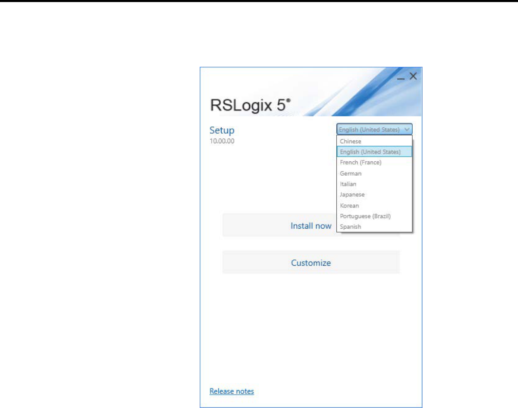
3. (optional) On the Welcome page, select a language to be shown during the
installation process. By default, your system language is selected.
4. To install all components available in the selected software using the
recommended settings, click Install now and go to step 11.
5. To select which components to install, click Customize.
6. On the Customize page, select the components. There may be two options
shown:
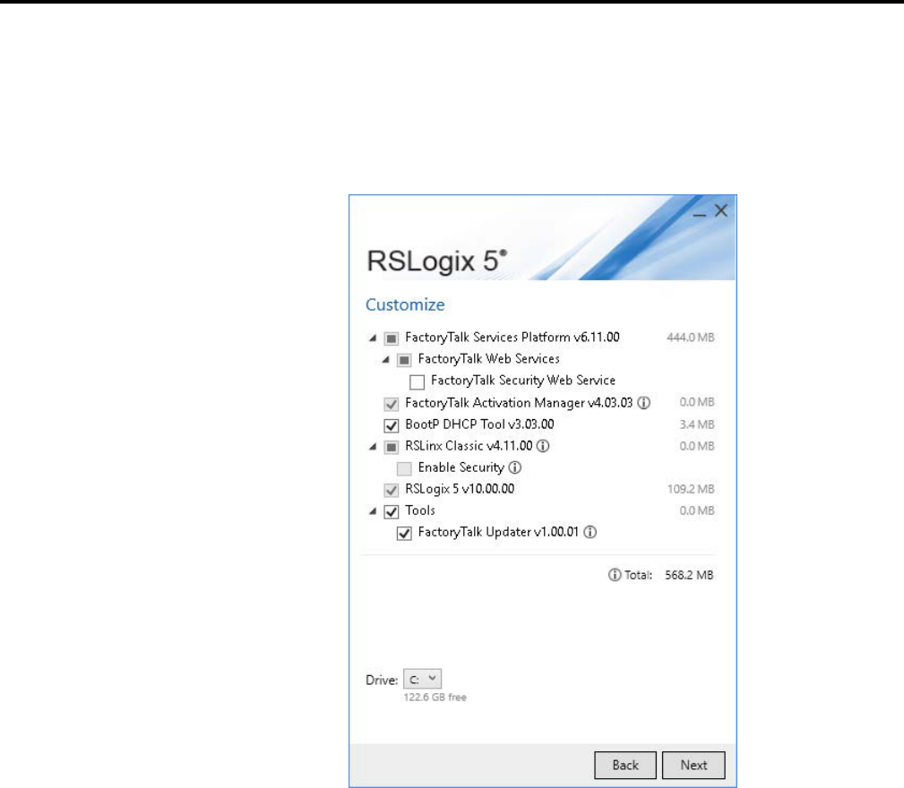
Installing and activating RSLogix 5
Chapter 1
Rockwell Automation Publication - LG5-GR002E-EN-P - December 2019 21
• Mandatory (grayed-out and selected check box) indicates software that
will be automatically installed as part of the selected application.
• Optional (clear check box) indicates software that you may wish to
include depending on your system. Select the box to include the
software during installation.
7. Select the location for Rockwell Automation software. The default location
is C:\.
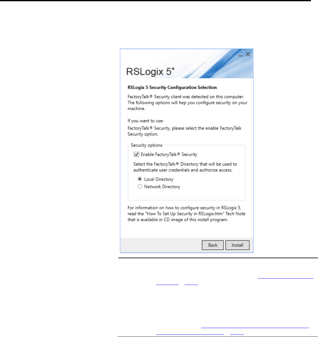
8. Click Next. The RSLogix 5 Security Configuration Selection page opens
only if you are installing RSLogix 5.
Chapter 1
Installing and activating RSLogix 5
22 Rockwell Automation Publication - LG5-GR002E-EN-P - December 2019
9. In the Security options box, select the options as needed. If you do not
want to use FactoryTalk Security, clear the Enable FactoryTalk® Security
check box.
Important:
If you select the Enable FactoryTalk® Security check box in the installation process, you
need to modify the FactoryTalk Security settings to restrict access to the RSLogix 5 functions.
For information about Configuring FactoryTalk Security, see
Configuring FactoryTalk Security
for RSLogix 5 on page 30.
If you accidentally turn on FactoryTalk Security and want to turn it off, you must uninstall
RSLogix 5, and then reinstall it.
If you have used the Rockwell Software Security Server to control user access to functions of
RSLogix 5 and you have turned on FactoryTalk Security, you can import your Security Server
database into FactoryTalk Security.
For more information, see
Importing a Security Configuration from the Rockwell Software
Security Server into FactoryTalk Security on page 28.
10. Click Install.
11. In the End User License Agreements dialog box, click Accept all to start
the installation, or click Decline to return to the last step.
Installing and activating RSLogix 5
Chapter 1
Rockwell Automation Publication - LG5-GR002E-EN-P - December 2019 23
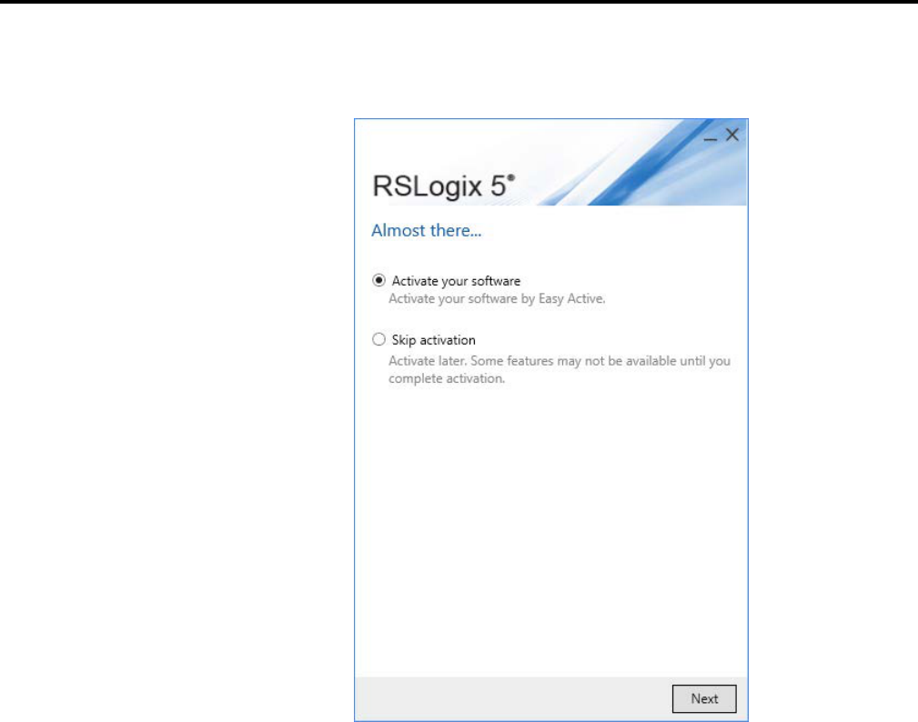
12. After the installation completes, the Activation page opens. You can
activate the software now or later.
13. To proceed directly to activate the installed software, select Activate your
software and then click Next, the Software Activation dialog box opens.
a. In the Serial number box, enter the serial number.
b. In the Product key box, enter the product key.
c. In the Earliest version box, select the earliest version of RSLogix 5 you
will use.
d. Select Activate locally or Activate using a dongle.
e. Click Continue.
You will be prompted to restart the computer after the activation.
Chapter 1
Installing and activating RSLogix 5
24 Rockwell Automation Publication - LG5-GR002E-EN-P - December 2019
14. To finish the installation without activation, select Skip activation and
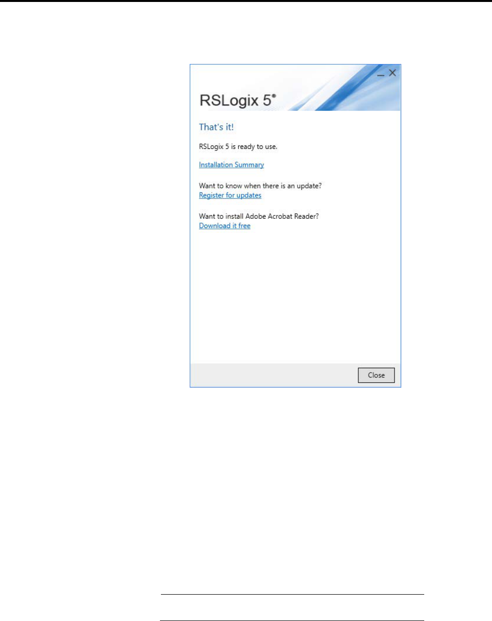
then click Next.
• To view the installation details, click Installation Summary.
• To receive the latest product updates and patch notification, click
Register for updates and subscribe.
• To install the latest version of Adobe® Acrobat® Reader®, click
Download it free and follow the on-screen instructions.
If you are upgrading the FactoryTalk Platform, there are procedures you must
follow to ensure that the platform will function properly.
To upgrade the automation system software on a stand-alone system that uses
a FactoryTalk Local Directory on a single computer
Important:
Uninstall all FactoryTalk-enabled products before uninstalling and
reinstalling the FactoryTalk Services Platform.
1. On the stand-alone computer where an earlier version of FactoryTalk
Services Platform is installed, shut down all running software products, and
Upgrading the FactoryTalk
Platform
Upgrading a Stand-Alone
System on a Single Computer

Installing and activating RSLogix 5
Chapter 1
Rockwell Automation Publication - LG5-GR002E-EN-P - December 2019 25
then uninstall all Rockwell Software products that depend on
FactoryTalk, such as RSView® SE Station, RSView® ME, RSLinx Classic,
RSLogix products, and so on.
2. Install FactoryTalk Services Platform v2.10.02.
The installation program prompts you for confirmation, and then
un-installs the earlier version of the FactoryTalk software before installing
the new version.
3. When the installation finishes, the FactoryTalk Directory Configuration
Wizard runs. On the first screen, click Next to select the default option,
Configure FactoryTalk Local Directory.
4. At the prompt to create an administrator account for this Local Directory,
either:
• Click Next to accept default user name and leave password blank —
recommended if you plan to override security services.
• Enter a user name and password — recommended if you plan to secure
your system with FactoryTalk Security. Remember that the password is
case sensitive.
5. Whether you accept the default user name and password entries or create
your own, write this information down and keep it in a safe place. You will
need these credentials to access the Local Directory and to log on to
FactoryTalk® Administration Console.
6. At the prompt to select who has full access to the Local Directory, choose
either:
• All users — recommended if you plan to override security services.
• Only administrators — recommended if you plan to secure your
system with FactoryTalk Security.
7. When the FactoryTalk Directory Configuration Wizard finishes, install the
software products that you plan to use in your stand-alone automation
system.
All of the participating FactoryTalk-enabled software products must also be
upgraded to versions that support Coordinated Process Release (CPR) 7.
For details, consult each product's installation documentation.

Chapter 1
Installing and activating RSLogix 5
26 Rockwell Automation Publication - LG5-GR002E-EN-P - December 2019
To upgrade the automation system software on a distributed system that uses
a FactoryTalk Network Directory across networked computers
1. Upgrade FactoryTalk Services Platform on the Network Directory Server
computer
2. Add computer accounts to the Network Directory Server
3. Upgrade FactoryTalk Services Platform on the remote client computers
Important:
Uninstall all FactoryTalk-enabled products before uninstalling and
reinstalling the FactoryTalk Services Platform.
1. On the computer that is hosting the FactoryTalk Network Directory
Server, shut down all running software products, and then uninstall all
Rockwell Software products that depend on FactoryTalk, such as RSView
SE Distributed, RSLinx Classic, RSLinx® Enterprise, RSLogix products,
RSSql™, and so on.
2. Install FactoryTalk Services Platform v2.10.02.
The installation program prompts for confirmation, and then un-installs
the earlier version of the FactoryTalk software before installing the new
version.
3. When the installation finishes, the FactoryTalk Directory Configuration
Wizard runs. On the first screen, select the Configure FactoryTalk
Network Directory check box, either accept or clear the Configure
FactoryTalk Local Directory check box, and then click Next to continue.
• In most cases, you do not need to configure a Local Directory when
upgrading a distributed system. To configure only a Network
Directory, clear the Configure FactoryTalk Local Directory check
box.
• If you plan to install RSBizWare Batch software on this computer, or if
you plan to install other stand-alone software, then you need both a
Network Directory and Local Directory configured on this computer.
Leave the Configure FactoryTalk Local Directory check box selected.
4. At the prompt to create an administrator account for this Network
Directory, enter a user name and password, and then write this information
down and keep it in a safe place. You will need these credentials to access the
Network Directory and to log on to FactoryTalk Administration Console.
Upgrading a Distributed
FactoryTalk System on a
Network
Upgrade FactoryTalk Services
Platform on the Network Directory
Server Computer

Installing and activating RSLogix 5
Chapter 1
Rockwell Automation Publication - LG5-GR002E-EN-P - December 2019 27
• Passwords are case sensitive.
• If you are configuring both a Network Directory and a Local Directory,
you will be prompted to create separate administrator accounts for each
directory.
5. At the prompt to select who has full access to the Network Directory,
choose either:
• Only administrators — recommended if you plan to secure your
system with FactoryTalk Security.
• All users — if you plan to override security by allowing all users full
access to your system.
6. Follow the steps in the wizard to finish configuring a Network Directory
(and optional Local Directory) on this computer.
7. Next, add a computer account to the Network Directory Server for each
remote client computer that is part of your distributed system. See the steps
below.
1. After installing FactoryTalk Services Platform and configuring a Network
Directory, run FactoryTalk Administration Console from the Windows
Start menu: Start > Programs > Rockwell Software > FactoryTalk
Administration Console.
2. At the prompt to choose a FactoryTalk Directory, choose Network, and
then log on, using the administrator user name and password you created
when you configured the directory.
3. In the Administration Console Explorer pane, open Network > System >
Computers and Groups > Computers. Create a computer account for
each remote client computer that is part of your distributed automation
system. For help, click Help on any dialog box.
4. Log off FactoryTalk Administration Console (File > Log off), and then log
off FactoryTalk (Start > Programs > Rockwell Software > FactoryTalk
Tools > Log On to FactoryTalk).
5. Next, upgrade FactoryTalk Services Platform on the client computers that
are part of your networked system. See the steps below.
1. On each of the client computers in your distributed system, shut down
all running software products, and then uninstall all Rockwell Software
products that depend on FactoryTalk, such as RSView SE Distributed,
RSLinx Classic, RSLinx Enterprise, RSLogix products, RSSql, and so on.
Add computer accounts to the
Network Directory Server
Upgrade FactoryTalk Services
Platform on the Remote Client
Computers

Chapter 1
Installing and activating RSLogix 5
28 Rockwell Automation Publication - LG5-GR002E-EN-P - December 2019
2. On each of the client computers, install FactoryTalk Services Platform
v2.10.02.
The installation program prompts for confirmation, and then un-installs
the earlier version of the FactoryTalk software before installing the new
version.
3. When the installation finishes, the FactoryTalk Directory Configuration
Wizard runs. On each screen, select the same options that you selected
when you configured the FactoryTalk Network Directory on the Network
Directory Server computer.
• On the first screen, select the Configure FactoryTalk Network
Directory check box, either accept or clear the Configure FactoryTalk
Local Directory check box.
• At the prompt to create an administrator account, enter the user name
and password of the administrator account you created when you
configured the directory on the Network Directory Server computer.
(Passwords are case sensitive.)
4. Next, on the various client computers on your network, reinstall the
software products that you plan to use in your distributed automation
system.
All of the participating FactoryTalk-enabled software products must also be
upgraded to versions that support Coordinated Process Release (CPR) 7.
For details, refer to each product's installation documentation.
If you have used the Rockwell Software Security Server to control access to user
actions in RSLogix 5 and you have enabled FactoryTalk Security, you can import
your security configuration from the Security Server into FactoryTalk Security.
The import process will import your users, user groups, and ACLs from the
Security Server, saving you time.
Tip:
After importing your security configuration into FactoryTalk Security, uninstall the
Security Server.
To import the security configuration from the Rockwell Software Security
Server into FactoryTalk Security
1. Because the import process writes to the FactoryTalk Directory, it is
important that you backup your FactoryTalk Directory before beginning
the import.
Importing a Security
Configuration from the
Rockwell Software Security
Server into FactoryTalk
Security

Installing and activating RSLogix 5
Chapter 1
Rockwell Automation Publication - LG5-GR002E-EN-P - December 2019 29
a. Run the FactoryTalk Administration Console by clicking Start >
Programs > Rockwell Software > FactoryTalk Administration
Console.
b. Log onto the FactoryTalk Directory where you are using FactoryTalk
Security.
c. Right-click the top-level object in the Explorer tree (this is the Network
or Local object, depending on whether you are viewing the Network or
Local directory), and then click Backup.
d. In the Backup window, type a name for the backup file in the Specify
archive name field. In the Specify archive location field, enter the
path to where you want to save the backup file. You can click the
browse (...) button to browse for a folder.
e. Click OK.
2. In the Rockwell Software Security Server Configuration Explorer, export
your security database to a file by clicking File > Export Database.
3. After exporting the database, close the Configuration Explorer.
4. Click Start > Programs > Rockwell Software > FactoryTalk Tools >
Import RSSecurity Configuration. This starts the FactoryTalk Security
Import utility.
5. In the import utility, enter the path to the file you exported from the
Security Server in the Select RS Security Server backup database to
import field. If you prefer, click Browse and locate the file.
6. From the Destination Directory pull-down list, select the FactoryTalk
Directory that you are using with FactoryTalk Security (Network or Local).
7. If you have actions in your Security Server database that do not have
security rights granted or denied, you can grant access to those actions to
users by default by checking the Add implicitly grant access box. If you do
not check this box, those actions will be denied to users by default.
8. If you want to display a log file of what happens during the import, check
the Display log on completion box.
9. Click OK.
10. The import utility warns that you should back up your FactoryTalk
Directory. If you have not done so, do so now (see step 1). If you have
backed up your FactoryTalk Directory, click Yes.

Chapter 1
Installing and activating RSLogix 5
30 Rockwell Automation Publication - LG5-GR002E-EN-P - December 2019
11. Log onto the FactoryTalk Directory where you will be using FactoryTalk
Security.
12. The import process runs. Depending on the contents of the file you are
importing and of your FactoryTalk Directory, you may receive a warning
message during the import. If this happens, review the information and
click OK to continue the import process.
13. When the process is complete, the import utility displays a window saying
whether it was successful or unsuccessful. Click OK.
14. If you chose to display a log file at the end of the import, the log file opens.
FactoryTalk Security allows you to control who can access features and functions
of RSLogix 5.
There are two methods for controlling access to the features and functions of
RSLogix 5:
• Policies, which are features and functions that are controlled globally.
When you set access rights to an RSLogix 5 policy, those rights affect users
without respect to the controllers they are using.
• Actions, which are features and functions that can be secured globally, but
can also be set on a controller-by-controller basis.
Configuring FactoryTalk
Security for RSLogix 5
Installing and activating RSLogix 5
Chapter 1
Rockwell Automation Publication - LG5-GR002E-EN-P - December 2019 31
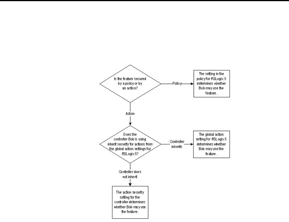
For example, we want to determine whether a user named Bob may use a given
function of RSLogix 5. To answer that question, we have to know whether the
feature is secured through a policy or through an action. If it is secured through an
action, we need to know whether the controller Bob is using inherits its security
settings from the global settings for RSLogix 5.
Chapter 1
Installing and activating RSLogix 5
32 Rockwell Automation Publication - LG5-GR002E-EN-P - December 2019
Security policies control features globally. If a user is granted access to a feature of
RSLogix 5 that is controlled by a policy, that user can use the feature regardless of
the controller the user is using.
RSLogix 5 security policies control the following features:
This policy: If granted to a user: If denied to a user:
Allow the installation of RSLogix Permits the user to install RSLogix 5. Prevents the user from installing
RSLogix 5.
Allow the un-installation of RSLogix Permits the user to uninstall RSLogix
5.
Prevents the user from uninstalling
RSLogix 5.
Change Report Settings Permits the user to change reporting
settings.
Prevents the user from changing
reporting settings.
Change Software Properties Permits the user to access and change
the software configuration options
(the Tools > Options menu item).
Also allows access to the properties
for ladder files, data table files, force
files, and database files.
Prevents the user from accessing or
changing software configuration
options.
Compare Utility Permits the user to use the Compare
utility.
Prevents the user from using the
Compare utility.
Setting Security Policies for
RSLogix 5

Installing and activating RSLogix 5
Chapter 1
Rockwell Automation Publication - LG5-GR002E-EN-P - December 2019 33
This policy: If granted to a user: If denied to a user:
Enable VBA Editor (RSLogix 5
Professional only)
Permits the user to use the Visual
Basic® for Applications (VBA) editor.
Prevents the user from using the VBA
editor.
Enable/Disable VBA (RSLogix 5
Professional only)
Permits the user to run VBA scripts. Prevents the user from running VBA
scripts.
Generate Report Permits the user to generate reports. Prevents the user from generating
reports.
Prompt for audit comment on File
New
RSLogix 5 prompts the user for a
comment when creating a new file (if
RSLogix 5 is configured to audit user
actions*).
The user is not prompted for a
comment when creating a new file.
Prompt for audit comment on File
Open
RSLogix 5 prompts the user for a
comment when opening a file (if
RSLogix 5 is configured to audit user
actions*).
The user is not prompted for a
comment when opening a file.
Prompt for audit comment on File
Save
RSLogix 5 prompts the user for a
comment when saving a file (if
RSLogix 5 is configured to audit user
actions*).
The user is not prompted for a
comment when saving a file.
*To enable auditing, you will need to install the optional source control software
for RSLogix 5. This software is available from Rockwell Software Technical
Support.
To set security policies for RSLogix 5
1. Start the FactoryTalk Administration Console by clicking Start >
Programs > Rockwell Software > FactoryTalk Administration Console.
2. If you are not automatically logged onto the FactoryTalk Directory Server,
log onto the server when prompted to do so. You must log onto the
FactoryTalk Directory using an administrator account (or an account that
has the rights to change security settings).
3. Once you are logged onto the server, click the System > Policies > Product
Policies > RSLogix 5 folder, and then open the Feature Security object.
Chapter 1
Installing and activating RSLogix 5
34 Rockwell Automation Publication - LG5-GR002E-EN-P - December 2019
Tip:
To be able to use RSLogix 5, users (or user groups) must have the Read right to the
Feature Security object for RSLogix 5. (To configure security for RSLogix 5, users
must be FactoryTalk administrators.)
If users do not have the Read right to the Feature Security object, the FactoryTalk
Directory will not allow them to read what rights they have in RSLogix 5, and
secured features will not function for those users.
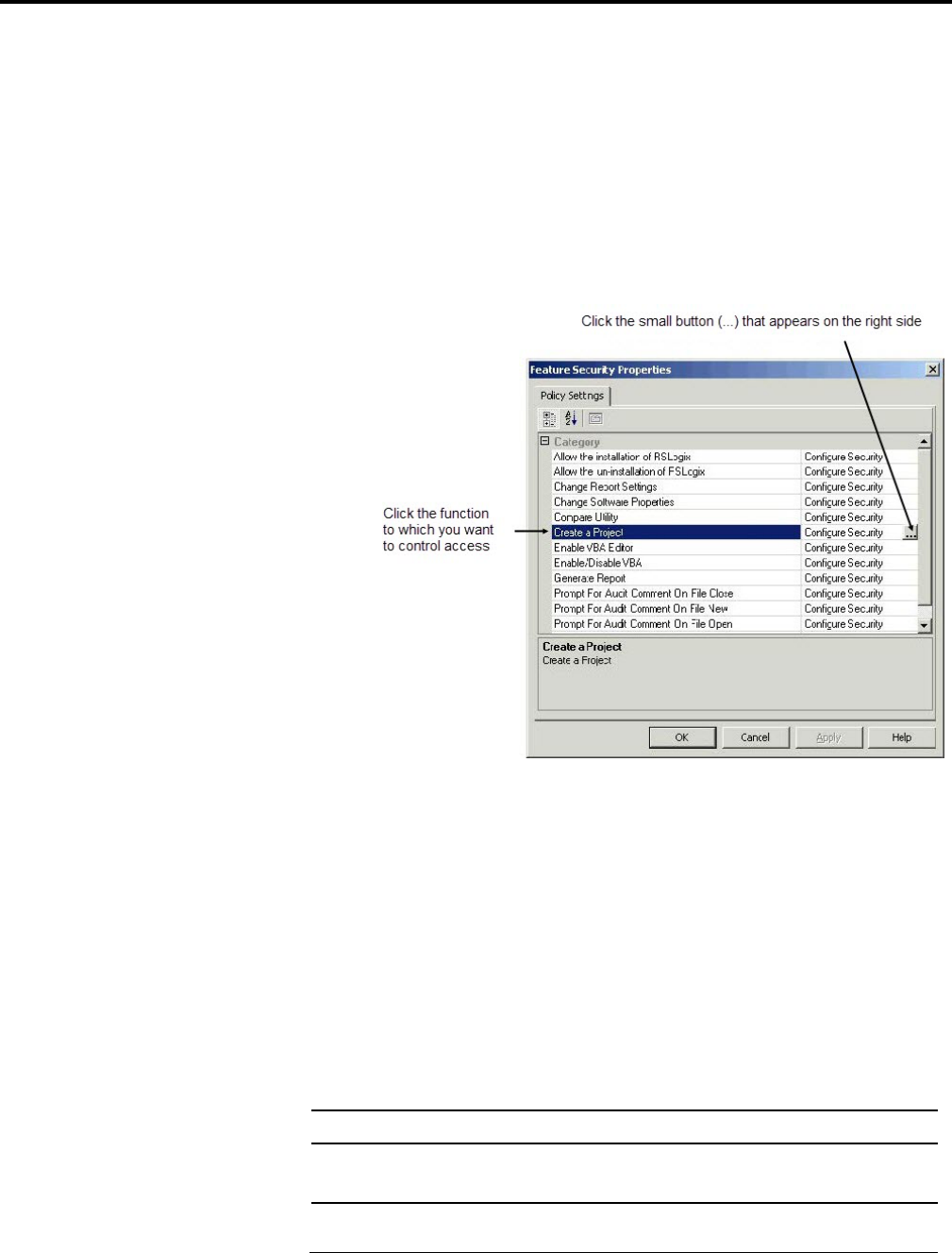
4. The Feature Security Properties window appears. In this window, click
the function to which you want control access, and then click the small
button (labeled ...) that appears on the right side of the window.
5. Configure the access for the function.
If you need more information about configuring FactoryTalk Security, click Help
on the Feature Security Properties window.
Secured actions are functions that are secured either globally (affecting all
controllers) or that are secured on a controller-by-controller basis. Whether the
security settings apply globally or not depends on whether controllers inherit their
security settings from the Networks and Devices object in the FactoryTalk
Directory.
The following actions can be secured for RSLogix 5:
This action: If granted to a user:
Change ControlNet XC File Association The user may change the XC file association for a
controller.
Change Password/Privilege Settings The user may change a controller's password/privilege
settings.
Securing Actions for RSLogix 5

Installing and activating RSLogix 5
Chapter 1
Rockwell Automation Publication - LG5-GR002E-EN-P - December 2019 35
This action: If granted to a user:
Change Privilege Class The user may change privilege classes for a controller.
Change Processor Mode The user may change controller modes.
Clear Fault The user may clear processor faults.
Clear Memory The user may clear controller memory.
Communications Configuration The user may configure controller communications.
Configure Hot-Backup The user may configure the hot backup feature for a
controller.
Create/Delete Custom Data Monitor The user may create or delete custom data monitors.
Create/Delete Data Files The user may create or delete data table files.
Create/Delete Program Files The user may create or delete program files.
Create/Delete Recipe Templates The user may create or delete recipe templates.
Create/Delete Trend The user may create or delete trends.
Create/Delete/Modify User Defined Structures The user may create, delete, and modify user defined data
structures.
Data File Properties The user may set the properties of data table files.
Data Table Modification The user may modify data table files.
Database Import/Export The user may import and export description databases.
Description Editing The user may edit the description database.
Download The user may download to a controller.
Force Functions The user may force I/O or modify forces.
Go Online The user may go online with a controller.
Load/Delete Logic Extension Modules The user may load or delete Logic Extension Modules
(LEMs)
Monitor Custom Data Monitors The user may monitor custom data monitors.
Monitor Recipe Templates The user may monitor recipe templates.
Monitor Trend The user may monitor trends.
Offline Data File Monitoring The user may monitor data table files while offline.
Offline Program File Editing The user may modify program files while offline.
Offline Program File Monitoring The user may monitor program files while offline.
Online Data File Monitoring The user may monitor data table files while online.
Online Program File Editing The user may modify program files while online.
Online Program File Monitoring The user may monitor program files while online.
Partial Download The user may use the partial download feature.

Chapter 1
Installing and activating RSLogix 5
36 Rockwell Automation Publication - LG5-GR002E-EN-P - December 2019
This action: If granted to a user:
Prevent Factory Password Override The user may override a controller’s password using the
factory override password.
Program File Properties The user may set the properties of program files.
Prompt for audit comment on applying port configuration If auditing is enabled*, the user will be prompted for a
comment when applying changes to controller port
configurations.
Prompt for audit comment on Assembling Pending Edits If auditing is enabled*, the user will be prompted for a
comment when assembling pending rung edits.
Prompt for audit comment on Changing Password If auditing is enabled*, the user will be prompted for a
comment when changing a controller password.
Prompt for audit comment on Changing Processor Mode If auditing is enabled*, the user will be prompted for a
comment when changing controller mode.
Prompt for audit comment on Channel Configuration
Data
If auditing is enabled*, the user will be prompted for a
comment when changing controller channel
configuration data.
Prompt for audit comment on Clearing all forces If auditing is enabled*, the user will be prompted for a
comment when clearing all forces in a controller.
Prompt for audit comment on Clearing Faults If auditing is enabled*, the user will be prompted for a
comment when clearing controller faults.
Prompt for audit comment on Clearing Memory If auditing is enabled*, the user will be prompted for a
comment when clearing controller memory.
Prompt for audit comment on Deleting Data File If auditing is enabled*, the user will be prompted for a
comment when deleting a data file.
Prompt for audit comment on Deleting Program File If auditing is enabled*, the user will be prompted for a
comment when deleting a program file.
Prompt for audit comment on Disabling all forces If auditing is enabled*, the user will be prompted for a
comment when disabling all forces.
Prompt for audit comment on Disabling SFC forces If auditing is enabled*, the user will be prompted for a
comment when disabling SFC forces.
Prompt for audit comment on Downloading program
from Processor
If auditing is enabled*, the user will be prompted for a
comment when downloading a program from a
controller.
Prompt for audit comment on Enabling all forces If auditing is enabled*, the user will be prompted for a
comment when enabling all forces.
Prompt for audit comment on Enabling SFC forces If auditing is enabled*, the user will be prompted for a
comment when enabling SFC forces.

Installing and activating RSLogix 5
Chapter 1
Rockwell Automation Publication - LG5-GR002E-EN-P - December 2019 37
This action: If granted to a user:
Prompt for audit comment on extended force data
clearing
If auditing is enabled*, the user will be prompted for a
comment when clearing external force files.
Prompt for audit comment on extended force data
configuration
If auditing is enabled*, the user will be prompted for a
comment when configuring external forces.
Prompt for audit comment on Going Offline If auditing is enabled*, the user will be prompted for a
comment when going offline.
Prompt for audit comment on Going Online If auditing is enabled*, the user will be prompted for a
comment when going online with a controller.
Prompt for audit comment on I/O auto configuration If auditing is enabled*, the user will be prompted for a
comment when autoconfiguring I/O.
Prompt for audit comment on Inserting a Replacement
Rung
If auditing is enabled*, the user will be prompted for a
comment when inserting a replacement ladder logic
rung.
Prompt for audit comment on Inserting a Rung If auditing is enabled*, the user will be prompted for a
comment when inserting a rung into a ladder logic
program.
Prompt for audit comment on Inserting Data File If auditing is enabled*, the user will be prompted for a
comment when creating a data table file.
Prompt for audit comment on Inserting Program File If auditing is enabled*, the user will be prompted for a
comment when creating a program file.
Prompt for audit comment on Loading from EEPROM If auditing is enabled*, the user will be prompted for a
comment when loading a program from EEPROM.
Prompt for audit comment on Marking Rung for Deletion If auditing is enabled*, the user will be prompted for a
comment when marking a rung for deletion.
Prompt for audit comment on Online Ladder Edits If auditing is enabled*, the user will be prompted for a
comment when editing ladder logic while online.
Prompt for audit comment on Partial Downloading
program from Processor
If auditing is enabled*, the user will be prompted for a
comment when using the partial download feature.
Prompt for audit comment on Partial Uploading program
from Processor
If auditing is enabled*, the user will be prompted for a
comment when using the partial upload feature.
Prompt for audit comment on processor name change If auditing is enabled*, the user will be prompted for a
comment when changing the name of a controller.
Prompt for audit comment on program file name change If auditing is enabled*, the user will be prompted for a
comment when changing the name of a program file.
Prompt for audit comment on reset of diagnostic counters If auditing is enabled*, the user will be prompted for a
comment when resetting diagnostic counters.
Prompt for audit comment on Rung Deletion If auditing is enabled*, the user will be prompted for a
comment when deleting a ladder logic rung.
Prompt for audit comment on scanlist modified If auditing is enabled*, the user will be prompted for a
comment when modifying a scanlist.
Prompt for audit comment on Storing to EEPROM If auditing is enabled*, the user will be prompted for a
comment when burning the EEPROM for a controller.
Prompt for audit comment on Testing Pending Edits If auditing is enabled*, the user will be prompted for a
comment when testing pending program edits.
Prompt for audit comment on Uploading program from
Processor
If auditing is enabled*, the user will be prompted for a
comment when uploading from a controller.
Replace The user may use the Replace function.
Save The user may save a project.

Chapter 1
Installing and activating RSLogix 5
38 Rockwell Automation Publication - LG5-GR002E-EN-P - December 2019
This action: If granted to a user:
Save/Delete User Workspace The user may save or delete user workspaces.
Transfer To/From EEPROM The user may burn or read from a controller's EEPROM.
Upload The user may upload a project from a controller.
View Extended Forces The user may view extended forces.
View User Defined Structures The user may view user defined data structures.
Offline Channel Configuration Editing The user may edit the channel configuration in offline
mode.
Online Channel Configuration Editing The user may edit the channel configuration in online
mode.
*To enable auditing, you will need to install the optional source control software
for RSLogix 5. This software is available from Rockwell Software Technical
Support.
When you configure access rights to securable actions, you can set them for all
controllers or for individual controllers. This section describes how to set security
for actions globally.
1. Start the FactoryTalk Administration Console by clicking Start >
Programs > Rockwell Software > FactoryTalk Administration Console.
2. If you are not automatically logged onto the FactoryTalk Directory Server,
log onto the server when prompted to do so. You must log onto the
FactoryTalk Directory using an administrator account (or an account that
has the rights to change security settings).
3. Once you are logged onto the server, right-click Networks and Devices,
and select Security.
4. The Security Settings for Networks and Devices window appears. In this
window:
Select the user or user group for which you want to configure access to
secured actions. (If you need to add a user or user group, click Add.)
a. Open the RSLogix 5 list by clicking the plus sign (+),
Setting security for actions globally
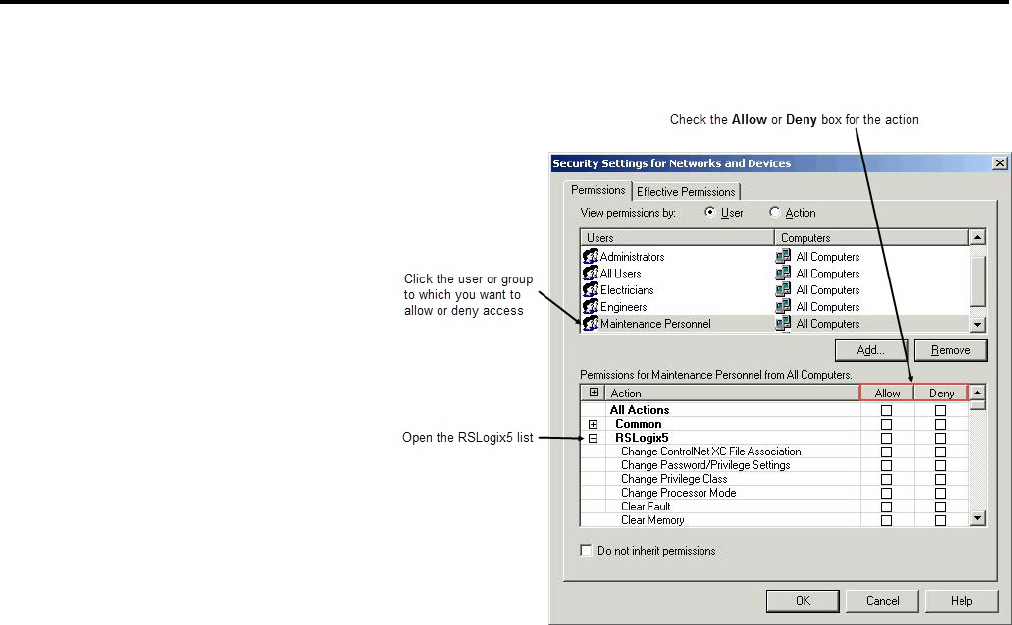
Installing and activating RSLogix 5
Chapter 1
Rockwell Automation Publication - LG5-GR002E-EN-P - December 2019 39
b. Check the Allow or Deny boxes for the actions.
If you need more information about configuring FactoryTalk Security, click Help
in the Security Settings for Networks and Devices dialog box.
Normally, controllers inherit their security settings from the settings for the
Networks and Devices object. However, you can break the inheritance chain for a
controller, configuring security for that controller separately. In that case, the
controller no longer inherits its security settings from the Networks and Devices
object.
To configure security for a controller so that it does not inherit its settings
from the Network and Devices object
1. Start the FactoryTalk Administration Console by clicking Start >
Programs > Rockwell Software > FactoryTalk Administration Console.
2. If you are not automatically logged onto the FactoryTalk Directory Server,
log onto the server when prompted to do so. You must log onto the
FactoryTalk Directory using an administrator account (or an account that
has the rights to change security settings).
3. Once you are logged onto the server, browse to the controller for which you
want to configure security for actions (under the Networks and Devices
object in the Administration Console’s Explorer tree). Right-click the
controller, and then click Security.
Setting security for actions on a
controller basis
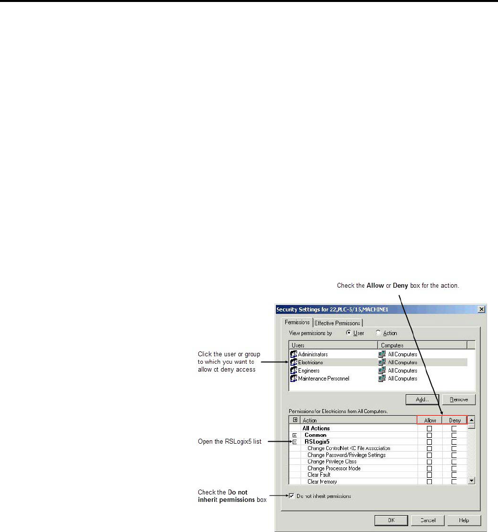
Chapter 1
Installing and activating RSLogix 5
40 Rockwell Automation Publication - LG5-GR002E-EN-P - December 2019
4. The Security Settings for Networks and Devices window appears. In this
window:
a. Check the Do not inherit permissions box. The software asks whether
you want to copy the permissions from the parent object (the Networks
and Devices object) or remove all inherited permissions from the object
(the controller). If you have already configured security for the
Networks and Devices object and want to use most of that
configuration for the controller, copy the permissions. Otherwise,
remove the inherited permissions.
b. Select the user or user group for which you want to configure access to
secured actions. (If you need to add a user or user group, click Add.)
c. Open the RSLogix 5 list by clicking the plus sign (+),
d. Check the Allow or Deny boxes for the actions.
To start RSLogix 5 software, click Start > Programs > Rockwell Software >
RSLogix 5 > RSLogix 5.
If RSLogix 5 does not start up or run properly:
• Do you have the correct version of RSLinx Classic installed? The software
requires RSLinx Classic version 2.51.00 or later.
Starting RSLogix 5 software
Troubleshooting
installation

Installing and activating RSLogix 5
Chapter 1
Rockwell Automation Publication - LG5-GR002E-EN-P - December 2019 41
• Does your computer have enough memory? Check the hardware
requirements on the first page of this chapter for memory requirements.
• Is the RSLogix 5 software activated? You will need to activate RSLogix 5
before you can use it.
• Do you have FactoryTalk Security or Security Server support enabled? If so:
• If FactoryTalk Security support is enabled, are you disconnected from
your network and unable to access your FactoryTalk Directory Server?
Is FactoryTalk Security configured to allow you to have access to
RSLogix 5 functions? Contact your FactoryTalk Security administrator
for more information.
• If Security Server support is enabled, are you disconnected from your
network and unable to access your Security Server(s)? Is the Security
Server configured to allow you to have access to RSLogix 5 functions?
Contact your Security Server administrator for more information.

Rockwell Automation Publication - LG5-GR002E-EN-P - December 2019 43
Chapter 2
Getting started with RSLogix 5
RSLogix 5 software is a 32-bit Windows ladder logic programming package for the
Allen-Bradley PLC-5 family of programmable logic controllers. RSLogix 5 is
compatible with programs created with any of Rockwell Software's PLC-5
programming packages.
RSLogix 5 software includes:
• A free-form ladder editor that lets you concentrate on the application logic
instead of proper syntax as you write your program
• A powerful project verifier that you use to build a list of errors you can
navigate to make corrections at your convenience
• Drag-and-drop editing to quickly move data table elements from one data
file to another, rungs from one subroutine or project to another, or
instructions from rung to rung within a project
• Search and replace to quickly change occurrences of a particular address or
symbol
• A point-and-click interface (project tree) that lets you access all the folders
and files contained in your project
• A custom data monitor to view separate data elements together and observe
interactions
• A histogram function to monitor a data table bit or word as either text or a
graphical timing chart
• SFC and Structured text editors, based on IEC 1131-3 standards, that share
the same simple drag-and-drop editing found in the common ladder logic
editor
• PC5 libraries for storing and retrieving portions of ladder logic for use
across any of Rockwell Software's PLC-5 programming software products
Overview of RSLogix 5
Navigating RSLogix 5
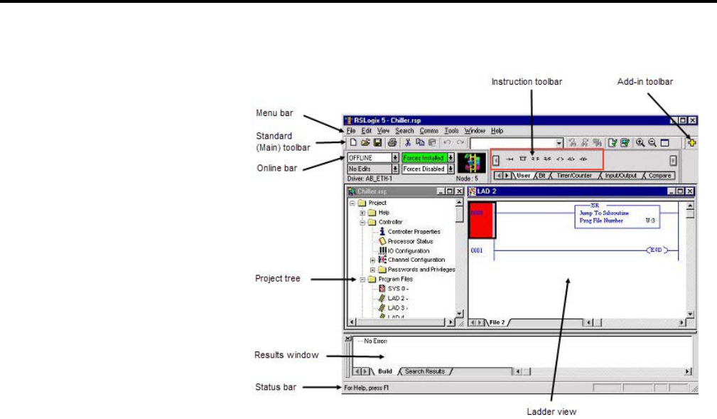
Chapter 2
Getting started with RSLogix 5
44 Rockwell Automation Publication - LG5-GR002E-EN-P - December 2019
RSLogix 5 includes the screen elements described below.
• Ladder view. In this part of the application window you can view several
program files at the same time. This is where you edit your ladder logic.
• Results window. Displays the results of a Find All search or a verification
procedure. You can hide this window view or drag it from the application
window and place it anywhere on your screen.
• Menu bar. Select functionality from the menus that appear as you click
each selection on this bar.
• Standard toolbar. The standard toolbar (also referred to as the main
toolbar) contains many functions that you will use repeatedly as you
develop and test your logic program. If you want to know what any of the
icons represent, RSLogix 5 can tell you. Just move your cursor to the icon. A
floating tooltip window will appear and tell you what the icon is used for.
• Online bar. Learn the operational mode and see whether you have online
edits or forces installed at a glance. You can even view the driver and node
number.
• Instruction toolbar. Displays instruction mnemonics in tabbed categories.
When you click on a category tab the instruction toolbar just above it
changes to show that category of instructions. Click an instruction to put it
in your ladder program.
• Add-in toolbar. In RSLogix 5 Professional only. Use this toolbar to quickly
access add-in software such as RSWire I/O Builder.
• Status bar. Look here for ongoing status information or prompts, as you
use the software.
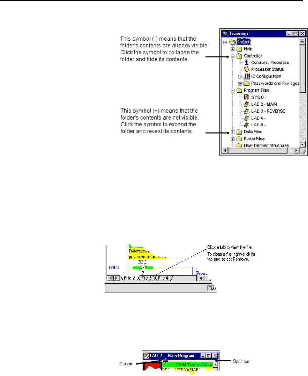
Getting started with RSLogix 5
Chapter 2
Rockwell Automation Publication - LG5-GR002E-EN-P - December 2019 45
• Project tree. Displays all the folders and files contained in your project.
If you right-click most items in the tree you will see a menu specific to the
item selected. For example, if you right-click on a program file, you see
options to rename, open, hide, or reveal properties of the program file,
among other things.
To open a program file, simply double-click the file in the project tree. To open
additional files, double-click each file that you want to open in the project tree. A
tab for each open program file appears at the bottom of the ladder view.
To open multiple files within the same project, you can split the viewing
window
1. Position the cursor on the split bar in the ladder view window. The pointer
turns into a double bar with two arrows.
2. Click and drag the split bar down to show two different viewing panes of
the program file.
Opening multiple program files
Splitting the viewing window

Chapter 2
Getting started with RSLogix 5
46 Rockwell Automation Publication - LG5-GR002E-EN-P - December 2019
3. With focus in either pane, double-click the program file in the project tree
that you want to view. The second file is opened on a tab in that pane.
Viewing two program files at once in this way makes drag and drop between
them easier. You can also display different sections of the same file in each
pane to facilitate moving or copying items within the same file.
Another method of viewing multiple program files is to open a separate window
for each.
1. In the project tree right-click on the program file you want to open.
2. Select New Window.
3. Repeat this process for any additional program files you wish to view
simultaneously.
To close a program window, click its close button
.
You cannot view program files from different projects with only a single instance
of the RSLogix 5 application software running on your computer. You must open
more than one instance of RSLogix 5 to work on multiple projects at the same
time. Once you have the projects opened, however, you can drag and drop
instructions and data between them.
The following steps explain how to get up and programming quickly with
RSLogix 5 as soon as you install it.
Of course, you will want your program to run in a controller. That means you will
need some way to connect your computer to your controller - and you will have to
tell the software how you are connected.
Communications from RSLogix 5 take place through another software package,
called RSLinx Classic. RSLogix 5 talks to RSLinx Classic, which in turn talks to
your communications devices.
A driver is a small piece of software that allows a computer to talk to other systems.
In this case, RSLinx Classic uses drivers to connect your computer to your
processor. You have to tell RSLinx Classic what driver you want to use to make
that connection.
The driver you use depends on the way your processor is physically connected to
your computer. There is a wide variety of possible physical connections; it's
important you know which type of connection your system is using and how that
physical connection is configured. For instance, if your processor is connected to
your network through another computer running RSLinx Classic Gateway, you
Opening multiple program windows
Quick Start steps for
development
Step 1 Configure a driver in
RSLinx Classic
Getting started with RSLogix 5
Chapter 2
Rockwell Automation Publication - LG5-GR002E-EN-P - December 2019 47
need to use an RSLinx Classic Gateway driver. If you are directly connected to
your processor through a 1784-KT card, you need to use the driver for that card.
You will also need to know the parameters of the physical connections - for
instance, if you are connecting through a 1784-KT card, you will need to know
how your KT card is configured and the station numbers of the processors on your
DH+ network.
Tip:
A "light" version of RSLinx Classic, called "RSLinx Classic Lite" comes with RSLogix
5. This version of RSLinx Classic provides the communication drivers necessary to
use RSLogix 5. RSLinx Classic Lite will not, however, provide communications
through DDE or OPC - those communication modes are used with other software
packages, such as HMI or data acquisition packages. To use DDE or OPC
communication, you will need to purchase RSLinx Classic.
To configure a driver in RSLinx Classic
a. Open RSLinx Classic by clicking Start > Programs > Rockwell
Software > RSLinx > RSLinx. RSLinx Classic starts in a minimized
mode - you will see an RSLinx icon in your Windows System Tray.
(The System Tray is a part of the Windows Taskbar - by default, the
System Tray is in the lower right-hand corner of your screen.) Click the
RSLinx icon to open the RSLinx window.
b. In RSLinx Classic, click Communications > Configure Drivers. This
opens the Configure Drivers window.
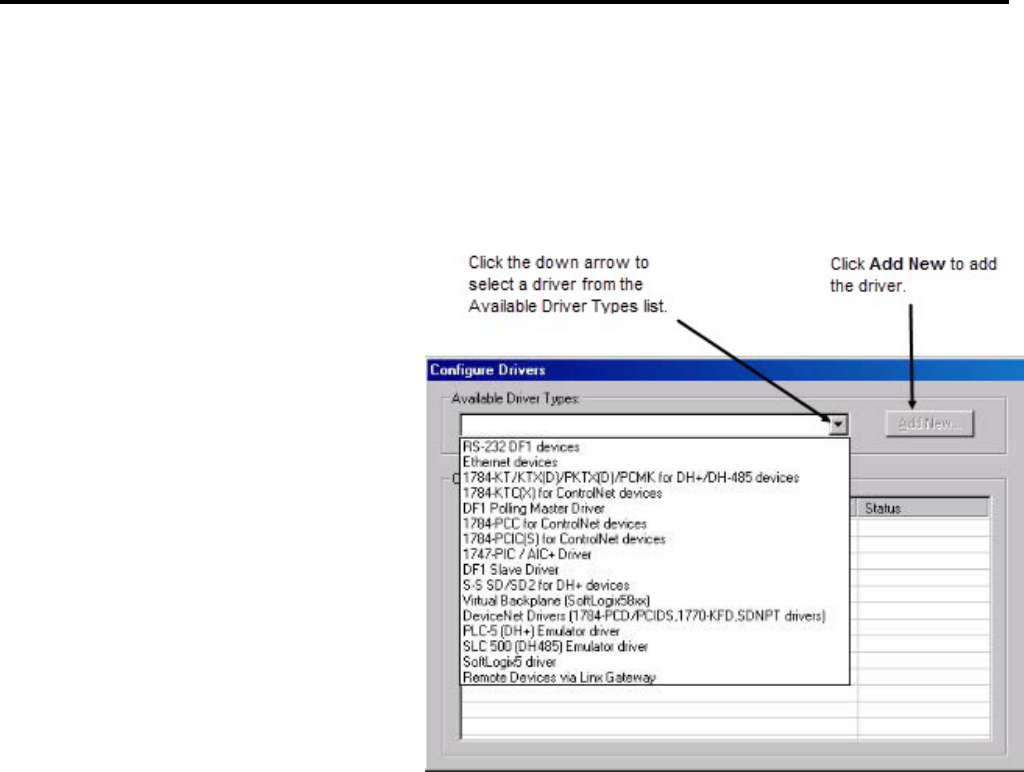
Chapter 2
Getting started with RSLogix 5
48 Rockwell Automation Publication - LG5-GR002E-EN-P - December 2019
c. In the Configure Drivers window, select the driver you need to use
based on your physical connection to the processor. For example, if you
are connecting with a 1784-KT card, select the
1784-KT/KTX(D)/PKTX(D)/PCMK for DH+/DH-485 devices
driver.
d. Click Add New to add the driver to the Configured Drivers list.
e. RSLinx Classic asks you to name the driver. RSLinx Classic uses this
name to refer to the driver. You can use the default name, or enter a
name (names can be up to 15 characters long). Click OK.
f. The window that appears next depends on the driver you selected. This
window is where you configure the driver. Configure the driver to
match your physical connection to the processor. If you need help with
the parameters for the driver, click Help on the window.
g. When you have finished configuring the driver, the driver appears in
the Configured Drivers list of the Configure Drivers window. Click
Close.
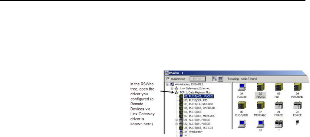
Getting started with RSLogix 5
Chapter 2
Rockwell Automation Publication - LG5-GR002E-EN-P - December 2019 49
h. You need to make sure the communications driver you configured is
working properly. To do this, use the RSWho function in RSLinx
Classic. This function shows what processors and other
communications devices are available through the driver. To display an
RSWho window, click Communications > RSWho.
i. In the RSWho tree, open the driver you configured. You should see the
processor to which you want to connect. If you can see the processor,
the driver is configured correctly and you can proceed to the next step.
If you cannot see the processor, the driver is not configured correctly
(or some other communication problem is preventing you from
accessing the processor). Correct the problem before proceeding. See
the online help in RSLinx Classic for information about the driver you
are using.
There are two kinds of communications configuration in RSLogix 5.
• System communications, which are set globally. When you set system
communications parameters, those parameters are the default for all new
projects in RSLogix 5.
• Controller communications, which are communications parameters
specific to a given project. When you set controller communications for a
project, those settings overwrite the system communications settings for
that project. (Other new projects still use the system communications
settings.)
Setting system communications parameters can save you time later. We suggest
you set the system communications parameters before creating your first project in
RSLogix 5.
Step 2 Configure system
communications
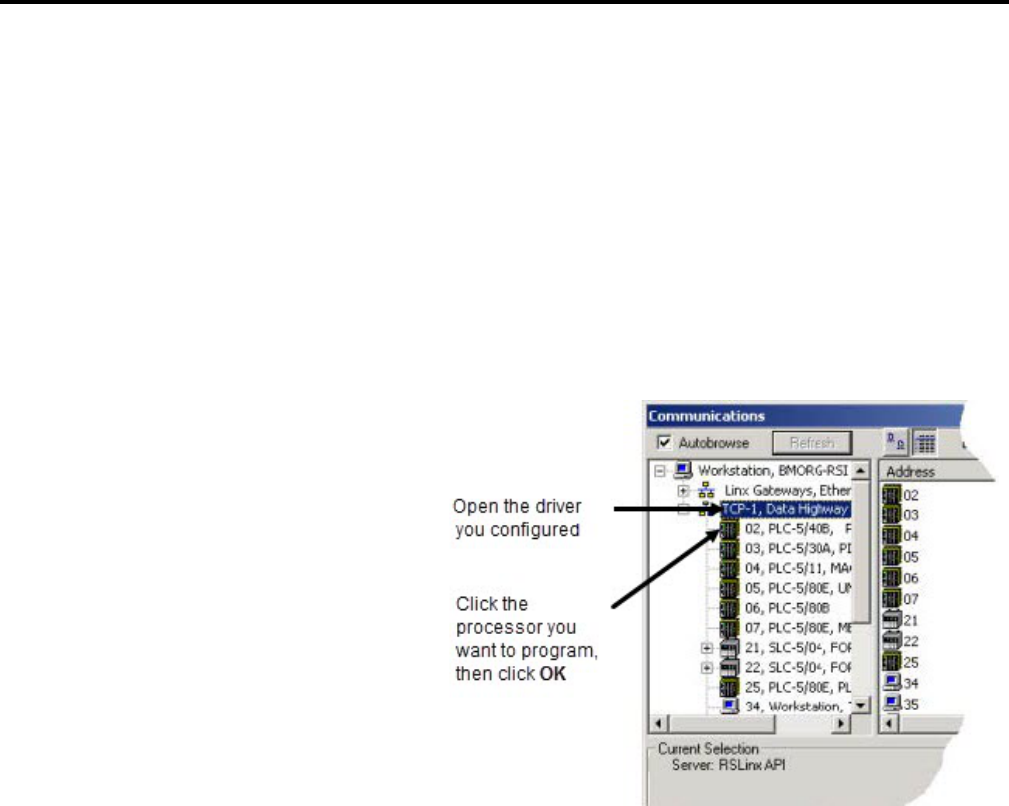
Chapter 2
Getting started with RSLogix 5
50 Rockwell Automation Publication - LG5-GR002E-EN-P - December 2019
To set the system communications parameters
a. From the Comms menu, click System Comms. This displays the
Communications window. (If RSLinx Classic is not running, it will
start.) The Communications window is very much like the RSWho
window you encountered while configuring your communications
driver.
b. In the Communications window tree, open the driver you configured.
The processor you want to program should be visible. Click the
processor, then click OK.
There is a great deal more that you can do from the Communications window.
For more information, see the online help.
Tip:
If you want to change the system communications settings, click Comms >
System Comms.
If you want to set different communications parameters for a given project but
leave the system communications settings alone, open the properties for the
project's controller. For more information, see the online help for RSLogix 5.
RSLogix 5 is based on projects. A project is the complete set of files associated
with your program logic.
To create a new project
1. Select File > New.
Step 3 Create a new project or
open an existing project
New Project

Getting started with RSLogix 5
Chapter 2
Rockwell Automation Publication - LG5-GR002E-EN-P - December 2019 51
2. Provide information about your processor on the Select Processor Type
dialog box. If you already set up communications as in Quick Start Step 1,
this information appears on the dialog box. If not, specify the
communications settings here. Click OK.
RSLogix 5 creates and displays the project tree control for your new project. This
project tree is your access point to program, data table, and database files. For more
information about the project tree, see Navigating RSLogix 5 on page 43
.
To open an existing project
1. Select File > Open.
2. Click the file you want to open and click Open. If the file you want to open
does not appear on the list:
• Use the Look in list to navigate to a different folder.
• Use the Files of type list to display files with an extension other than
.RSP, .X5, .PC5, or .AF5.
RSLogix 5 can open projects and documentation files that were developed using
any Rockwell Software DOS-based (PLC-5 A.I. Series or 6200 Series PLC-5) or
Windows-based (RSLogix 5 or WINtelligent™ Logic 5) programming software. If
you experience a problem however, there are special considerations that may affect
retrieval of your database files. For more information about opening projects
created using other Rockwell Software PLC-5 programming software products,
see Chapter 3, Opening A.I. and 6200 project files in RSLogix 5 on page 61
.
Tip:
For clarification of the different file types and their extensions, click Help on the
Open/Import PLC-5 Program dialog box.
To add a chassis
1. From the Controller folder in the project tree, double-click the IO
Configuration icon. The I/O Configuration - Chassis Table dialog box
appears.
2. Right-click inside the I/O Configuration dialog box and select Add
Chassis. The Edit Chassis Properties dialog box appears, with the Chassis
tab selected.
3. Select the chassis type by clicking one of the option buttons. A list is
displayed showing the available chassis.
4. Select the desired chassis from the list.
Existing Project
Step 4 Add the chassis and I/O
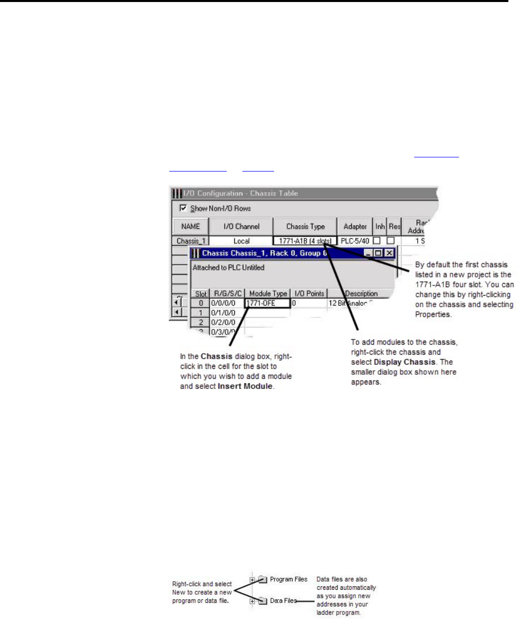
Chapter 2
Getting started with RSLogix 5
52 Rockwell Automation Publication - LG5-GR002E-EN-P - December 2019
5. If you've selected a Flex I/O chassis, enter the number of slots in the
Number of slots field. Enter a value from 1 to 8.
6. Document the DIP switch settings by selecting the configuration settings in
the pull-down list boxes in the DIP Switches section of the dialog box.
7. Click OK to accept your choices and close the dialog box.
Some modules may require configuration after they have been added. For more
information about hardware configuration, see Chapter 4,
Hardware
configuration on page 63.
ControlNet™ users: For ControlNet processors controlling I/O via ControlNet,
the chassis and modules must first be mapped in RSNetWorx before they will
appear in the chassis table to be configured. Also, the associated .XC file (created
by RSNetWorx™) and the ControlNet node number of the processor must be
entered in Controller Properties in the Project Tree.
The project tree is your point-of-entry for creating new files or accessing existing
files. To create a new file, right-click the program or data file icon and then select
New. A dialog box appears for you to provide information about the file. For
more information, refer to the online help.
A program file may contain controller information (SYS 0), the main ladder
program (LAD 2), or a subroutine program.
Step 5 Create program and data
table files
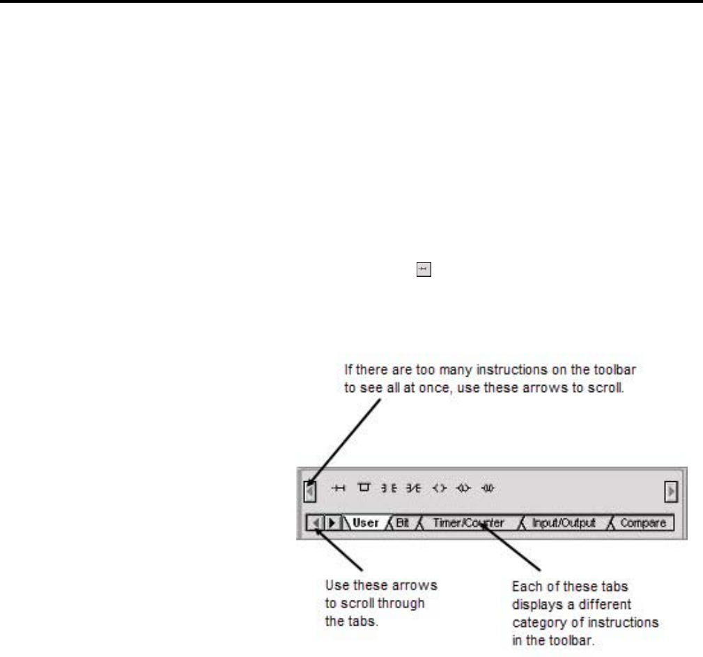
Getting started with RSLogix 5
Chapter 2
Rockwell Automation Publication - LG5-GR002E-EN-P - December 2019 53
Data table files contain the status information associated with external I/O and all
other instructions you use in your main and subroutine ladder program files. In
addition, these files store information concerning controller operation. You can
also use data table files to store look-up tables if needed.
When you open a program file by double-clicking its icon in the project tree, the
ladder file opens in the right half of the RSLogix 5 window. Usually program file
#2, the main program file, is opened when you open a project. If you have not
begun to enter any ladder logic, only the end rung will show.
To enter ladder logic to a new program
1. Click the end rung icon
and then select the new rung icon on the User
tab of the instruction toolbar.
2. To place an instruction on a rung, click its icon on the instruction toolbar.
You can place several instructions on a rung in sequence by clicking the
icons one after another. RSLogix 5 places instructions from left to right.
3. Assign an address to each instruction. Double-click an instruction, type the
address in the empty field that appears above the instruction, then press
Enter. With RSLogix 5 you can also drag and drop addresses from a data
table file onto instructions in your ladder logic.
4. Continue adding rungs, remembering to save your file periodically with File
> Save.
RSLogix 5 supports a file-based editor. This means that you can:
• Create and/or edit multiple rungs at a time
Step 6 Enter a logic program

Chapter 2
Getting started with RSLogix 5
54 Rockwell Automation Publication - LG5-GR002E-EN-P - December 2019
• Enter addresses before you actually create data table files for your I/O
• Enter symbols before you have assigned addresses for them in the database
• Enter instructions without having to provide addresses until just before file
validation occurs
For more detailed information about entering ladder logic including information
about shortcuts, branching, addressing, and performing program edits online, refer
to Chapter 6, More about entering ladder logic on page 77
.
You can use several methods to add symbols and descriptions to addresses in the
database.
• Add a symbol directly to an addressed instruction in the ladder logic.
Double-click the address, type the symbol in the address edit field, and press
Enter.
You can enter a symbol in this manner before an address has been assigned,
then later use the database editor to assign an address. (Database editor is an
encompassing term for the various database editing dialog boxes that appear
when you click one of the icons under Database in the project tree.)
• Right-click an instruction address or rung number in the ladder logic and
select Edit Symbol or Edit Description for an address or Edit Comment
or Edit Title for a rung.
• Modify an address's symbol and description in the data file. Double-click
the data file in the project tree, click on an address in the table. The bottom
of the dialog box contains fields where you can enter the documentation for
the address.
• Modify (add, delete, change) the database using the database editor. This is
the preferred method for deleting project documentation. All
documentation (including instruction comments and group names and
descriptions) can be edited with this method. Double-click an icon in the
database folder located in the project tree. Another method of accessing the
database editor is to right-click an address in the ladder logic and select
Goto DataBase.
• Copy symbols and descriptions from the ladder display between RSLogix 5
and RSLogix 500 or between instances of RSLogix 5 by using cut, copy, and
paste options or by dragging and dropping the symbol or description from
one application to another. (A dialog box will appear if there is a database
collision.) Any errors or inconsistencies between data types will be flagged
when the program is verified. You cannot copy and paste to other
applications within the database editor, only from within the ladder view.
• Use Microsoft Excel® to edit the database. Select Tools > Database > Edit
Using Excel. (This feature is available only in RSLogix 5 Professional.)
Step 7 Add documentation to
your logic instructions
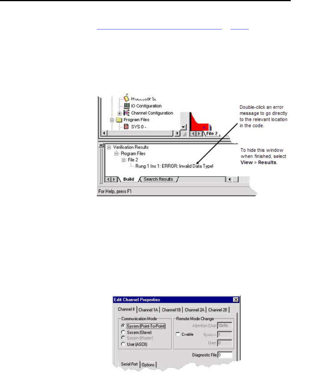
Getting started with RSLogix 5
Chapter 2
Rockwell Automation Publication - LG5-GR002E-EN-P - December 2019 55
For information about database import and export options, see Chapter 5,
Importing or exporting the documentation database on page 69.
When you are ready to build your project, you can validate a single program file or
you can validate your entire project. Select Edit > Verify File or Verify Project.
After you initiate a verification, the Verify Results output window displays and
gives you information about mistakes or omissions that may have occurred as you
wrote your program logic.
Enhanced (New Platform), Protected (Secure), Ethernet, and ControlNet PLC-5
processors have communication channels that must be configured. (For Soft
Controllers, configure the PLC-5 I/O, Remote I/O scan list, and SLC™ 500 I/O.
Double-click the appropriate icons under IO Configuration in the project tree.)
To configure communication channels
1. Double-click the Channel Configuration icon in the Controller folder in
the Project tree.
2. Edit the properties in the dialog box and click OK.
• Use the Channel 0 tab to configure settings for RS232/422/423.
Step 8 Verify the program logic
Step 9 Configure the
communication channels
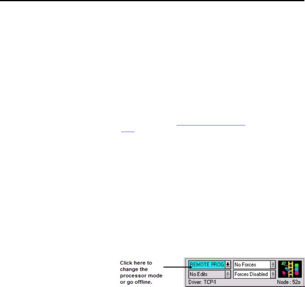
Chapter 2
Getting started with RSLogix 5
56 Rockwell Automation Publication - LG5-GR002E-EN-P - December 2019
• Use the Channel 1A - 2B tabs for DH+, Scanner, Adapter, or Inactive I/O
channel mode.
• Use the Channel 2 tab (not shown) for Ethernet or Local I/O Extension
channels.
• Use the Channel 3A tab (not shown) when using a VME or Ethernet
sidecar coprocessor.
• For more information about the parameters in the dialog box, click Help or
press F1.
Tip:
If you are developing the program offline, for example on a laptop remote from
the site, and later plan to download and run the program on a specific processor
(node) via a determined protocol, you may want to override system
communication settings made in Step 2 Configure system communications
on
page 49. Double-click Controller Properties in the project tree, click the
Controller Communications tab, and set the communication settings. Settings
made on this dialog box will override any driver and node settings established in
Step 2, and should be completed before performing this step.
To download and go online
1. Select Comms > Download to download the current offline program into
the controller.
2. RSLogix 5 automatically verifies the project. If no errors are found, the
download continues. If errors are found, you must correct them and initiate
the download again (with Comms > Download).
3. After downloading, RSLogix 5 will ask if you want to go online. Click Yes
to go online.
If you want to download only specific program and data files, force data, or
channel configuration data, select Comms > Partial Download. This allows you
to maintain certain parts of your PLC-5 program, while overwriting other parts.
You can use RSLogix 5 to watch what is happening in your data table files. This
procedure is called monitoring data table files.
When you are monitoring data table files, you can:
• Define how your data file selection grid will display
• Change values in the data table
• Change the display radix
Step 10 Download and go
online
Step 11 Monitor data files

Getting started with RSLogix 5
Chapter 2
Rockwell Automation Publication - LG5-GR002E-EN-P - December 2019 57
• Show which addresses are used in your ladder logic
• Switch between files
• Quickly jump to another address in another data table file
• Cross reference data
To monitor data, simply open a data file (double-click it) in the project tree. You
can have multiple data table files opened for monitoring at the same time. To
cascade or tile all the windows opened in your RSLogix project, select an option
from Window > Arrange.
Data changes made offline only affect the disk file unless the program is restored to
the processor.
Data changes made online only affect the processor file unless the program is saved
or uploaded while online to update the disk file.
For information about how you can perform a cross reference, force I/O, or create
and monitor lists of related addresses instead of accessing the data table files, see
Chapter 7, More about monitoring data on page 89
. Also, you can use histograms
to monitor a data table bit or word as either text or a graphical timing chart. More
information about histograms can be also be found in Chapter 7.
The Find option allows you to quickly locate instructions, addresses, and symbols
in ladder program files. You can even search for edit zones within your logic
program. If you want to automatically replace instructions and addresses with
different ones, you can use the Replace option. You can use wildcards in your find
and replace operations.
To search (and replace)
1. Select Search > Find or Search > Replace.
2. Specify the instruction you want to locate in the Find What field. You can
type any of the following:
• The mnemonic (such as XIC or TON)
• The address (such as B3/4)
• A combination of both mnemonic and address (XIC B3/4)
• A combination of mnemonic and symbol (XIC REPEAT)
3. If replacing, type what you want the instruction replaced with in the
Replace With field.
Step 12 Search and replace
instructions
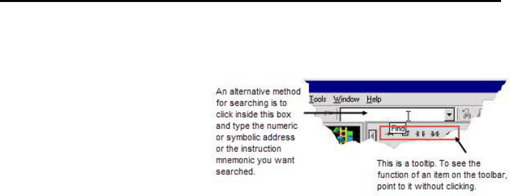
Chapter 2
Getting started with RSLogix 5
58 Rockwell Automation Publication - LG5-GR002E-EN-P - December 2019
4. Set remaining parameters in the dialog box if desired (such as the search
direction) and click Find Next or Replace. For more information about the
options and buttons in the dialog box, click Help.
You can obtain a printout of various elements of your project, such as program
files, data table files, and processor information.
To print a report
1. Select File > Report Options. The Report Options dialog box displays a
tree on the left with the elements of a report that you can configure (such as,
which program files to print, title, header, fonts, colors, etc.). The right side
of dialog box displays the controls for you to set.
2. Use the check boxes to mark everything you want included in the report.
3. Click Page Setup to set the paper size, margins, and orientation.
4. In the tree, click an element to configure that element's settings. For
example, when you click Program Files in the tree, the options on the
dialog box allow you to select which program files you would like to print
and even ranges of rungs.
If you are including a title page, header, and footer, be sure to click each of
these elements in the tree to set them up.
5. Click Print Preview to see how the report will appear. You can scale up the
image to make the information appear larger on the printed page or scale
down the image so that, in cases where many instructions are on a rung of
logic, all the instructions can fit on the printed page.
6. If the report appears as you expected, click Print to print the report.
Otherwise, click Options to return to the Report Options dialog box and
make changes.
If you wish to save report settings for future use, click Save/Load at the
bottom of the Report Options dialog box. Notice that the Report Options
Setup Load/Save dialog box that appears has an Import and an Export
Step 13 Print a report

Getting started with RSLogix 5
Chapter 2
Rockwell Automation Publication - LG5-GR002E-EN-P - December 2019 59
button allowing you to import and export report formats for use with other
projects.
The steps below will help you get online quickly for maintenance tasks, like, for
example, changing some contacts.
Tip:
RSLogix 5 now provides a feature for going online more quickly called Online
Now. System communications must be configured. Select Comms > Online
Now. If the offline program file is different from that in the processor, the
processor file is uploaded automatically. The database is not loaded and x-ref is
disabled. More information is available in the online help.
This step assumes that a driver has been configured in RSLinx Classic or RSLinx
Classic Lite. If not, do so before performing this step. For more information on
configuring drivers, see the online help in RSLinx Classic. (Select driver
configuration in the RSLinx Classic help index).
1. Select Comms > Who Active Go Online.
2. Use the tree structure in the left pane to navigate to the network on which
the processor resides.
3. Click the processor in the right pane to select it.
1. Click Online.
2. The system checks for a project on your computer that matches the
processor program. One of three things will happen:
• A perfect match is found. In this case, RSLogix 5 goes online with no
further action required on your part.
• An imperfect match is found for one or more projects with the target
processor name. In this case, select the desired project file from the list
and click Upload Logic, Merge with Existing File's Comment /
Symbol DB.
• No match is found. In this case, click Create New File.
Quick Start steps for
maintenance
Step 1 Establish
communications with the
processor
Step 2 Go online

Rockwell Automation Publication - LG5-GR002E-EN-P - December 2019 61
Chapter 3
Opening A.I. and 6200 project files in RSLogix 5
RSLogix 5 can open projects and documentation files that were developed using
any RSI DOS-based (PLC-5 A.I. Series or 6200 Series PLC-5 or Windows-based
(RSLogix 5 or WINtelligent Logic 5) programming software. If you experience a
problem however, there are special considerations that may affect retrieval of your
database files.
If the procedure below does not satisfactorily open the ladder logic file and its
accompanying database files, read and follow the special considerations for PLC-5
A.I. Series software and 6200 Series PLC-5 programming software discussed in
this chapter.
1. Select File > Open.
2. Use the Look In box to navigate to the location of the project file.
3. In the Files of Type field, select the type of project. RSLogix 5 supports
.RSP, .X5, .AF5 and .PC5 library files, as well as backup files.
4. Click the project file you want to open, and click Open.
When you open an X5 project created using PLC-5 A.I. Series programming
software, RSLogix 5 automatically imports the documentation database making it
available to the X5 file. If however, for some reason, the documentation database
cannot be accessed or fails to accompany the project, you can attach the
documentation using the method below.
Make sure your have followed the procedure above for opening a project before
proceeding with the following steps.
1. With the project opened, select Tools > Database > Native Import.
2. Select AI for the Import input format.
3. Select which types of data to import and specify what to do in case of
collisions with existing data records. Press F1 if you need help on the dialog
box.
4. Click OK.
5. Find the .DSC file for your project; click it to select it.
Opening a Project File
Special Considerations
Retrieve the PLC-5 A.I. Series
documentation database

Chapter 3
Opening A.I. and 6200 project files in RSLogix 5
62 Rockwell Automation Publication - LG5-GR002E-EN-P - December 2019
6. Click Open. The data you specified will be imported into the current
project.
When you attempt to open an AF5 project created using DOS-based 6200 Series
PLC-5 programming software, RSLogix 5 does two things. It automatically
launches an internal conversion utility that converts the AF5 file into an
X5-format file. Then it imports the documentation database making it available to
the X5 file.
Sometimes, due to the complexity of your project or the software version used to
create it, you may experience a problem with this process. You may find that
RSLogix 5:
• Cannot retrieve the database documentation associated with the file
(corrupt database message)
• Has problems opening the AF5 project file
If this happens, follow the procedure below to open the 6200 Series PLC-5 project
file including the documentation database.
1. Using the 6200 Series DOS programming software, save the 6200 Series
PLC-5 project file as an X5 file.
2. In RSLogix 5, select File > Open.
3. Use the Look In box to navigate to the location of the project file.
4. In the Files of Type field, select PLC5 Programs (*.X5).
5. Click the project file you want to open, and click Open. (The
documentation will not follow. It must be imported as described next.)
6. Select Tools > Database > Native Import.
7. Select AB 6200 for the Import input format.
8. Make sure Import ALL is selected.
9. Click OK.
10. Use the Look in box to navigate to the location of the 6200 Series PLC-5
database files (OP$ extension). Click the database file, and then click Open.
Open a 6200 Series PLC-5
Project
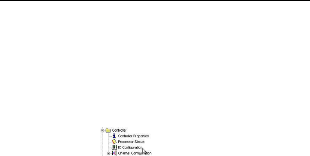
Rockwell Automation Publication - LG5-GR002E-EN-P - December 2019 63
Chapter 4
Hardware configuration
This chapter provides information on configuring your chassis and I/O modules
in RSLogix 5.
The chassis table is the starting point for adding, deleting, or configuring chassis,
processors, adapters and I/O modules. To display this window double-click the
I/O Configuration icon in the project tree.
Use the right mouse button menus to perform tasks in the Chassis Table.
The chassis table contains information about the current configuration of your
I/O chassis, including:
• The chassis type
• The processor (or adapter) for the chassis
• Whether the chassis is inhibited or reset
• The rack addressing mode for the chassis
• The rack, group, and slots encompassed by the chassis
• Whether the chassis is set to use complementary I/O
For clarity, you can limit your view of the chassis table to only show rows having
directly to do with I/O - that is, the chassis and I/O scanner rows. To do this, clear
the Show Non-I/O Rows check box at the top of the chassis table.
By default each processor in your project is associated with one I/O chassis. You
can add additional chassis to a processor to expand the number of I/O modules
that processor can address. Adding a chassis consists of selecting the type of chassis
you are using for your project and documenting the chassis DIP switch settings.
ControlNet users: For ControlNet channels, first use RSNetWorx to insert,
delete and modify chassis and modules. Then use RSLogix 5 to configure the
modules.
The chassis table
Adding and configuring a
chassis
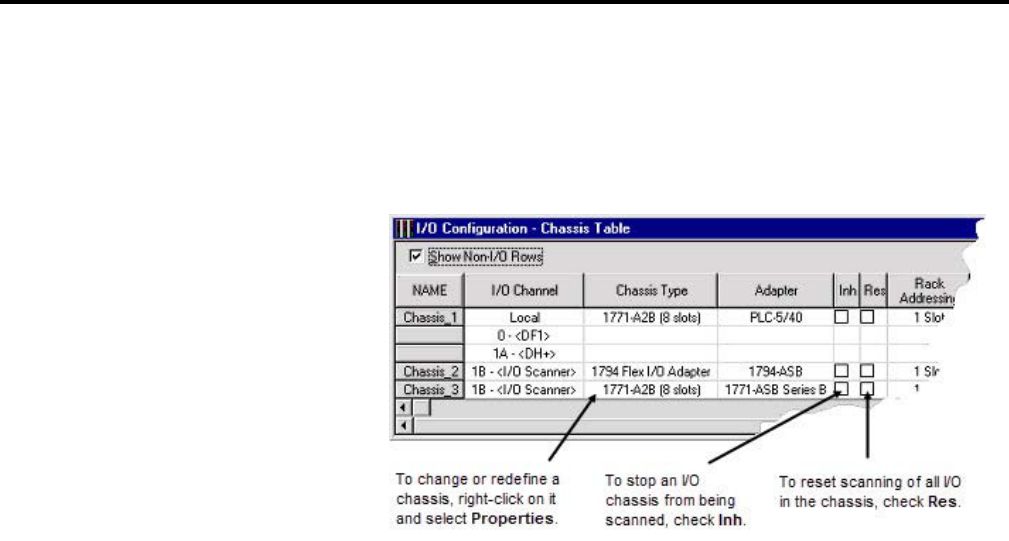
Chapter 4
Hardware configuration
64 Rockwell Automation Publication - LG5-GR002E-EN-P - December 2019
To add and configure a chassis
1. From the Controller folder in the Project tree, double-click the I/O
Configuration icon. The I/O Configuration - Chassis Table dialog box
appears.
2. Right-click in the Chassis Table and select Add Chassis. The Edit Chassis
Properties dialog box appears, with the Chassis tab selected.
3. Select the chassis type by clicking one of the option buttons. A list is
displayed showing the available chassis.
4. Select the desired chassis from the list.
5. If you've selected a Flex I/O chassis, enter the number of slots in the
Number of slots field. Enter a value from 1 to 8.
6. Document the DIP switch settings by selecting the configuration settings in
the pull-down list boxes in the DIP Switches section of the dialog box.
7. Click Apply to accept your choices and leave the dialog box open or click
OK to accept your choices and close the dialog box.
Each I/O chassis has an I/O adapter. The adapter is either a PLC-5 processor,
configured when you begin a project, or an I/O adapter. Select chassis DIP switch
settings, add or change the type of adapter, or establish configuration settings for
the adapter in any chassis by double-clicking on the processor or adapter in the
Chassis Table (or right-clicking and selecting Properties).
Configuring a PLC or I/O
adapter
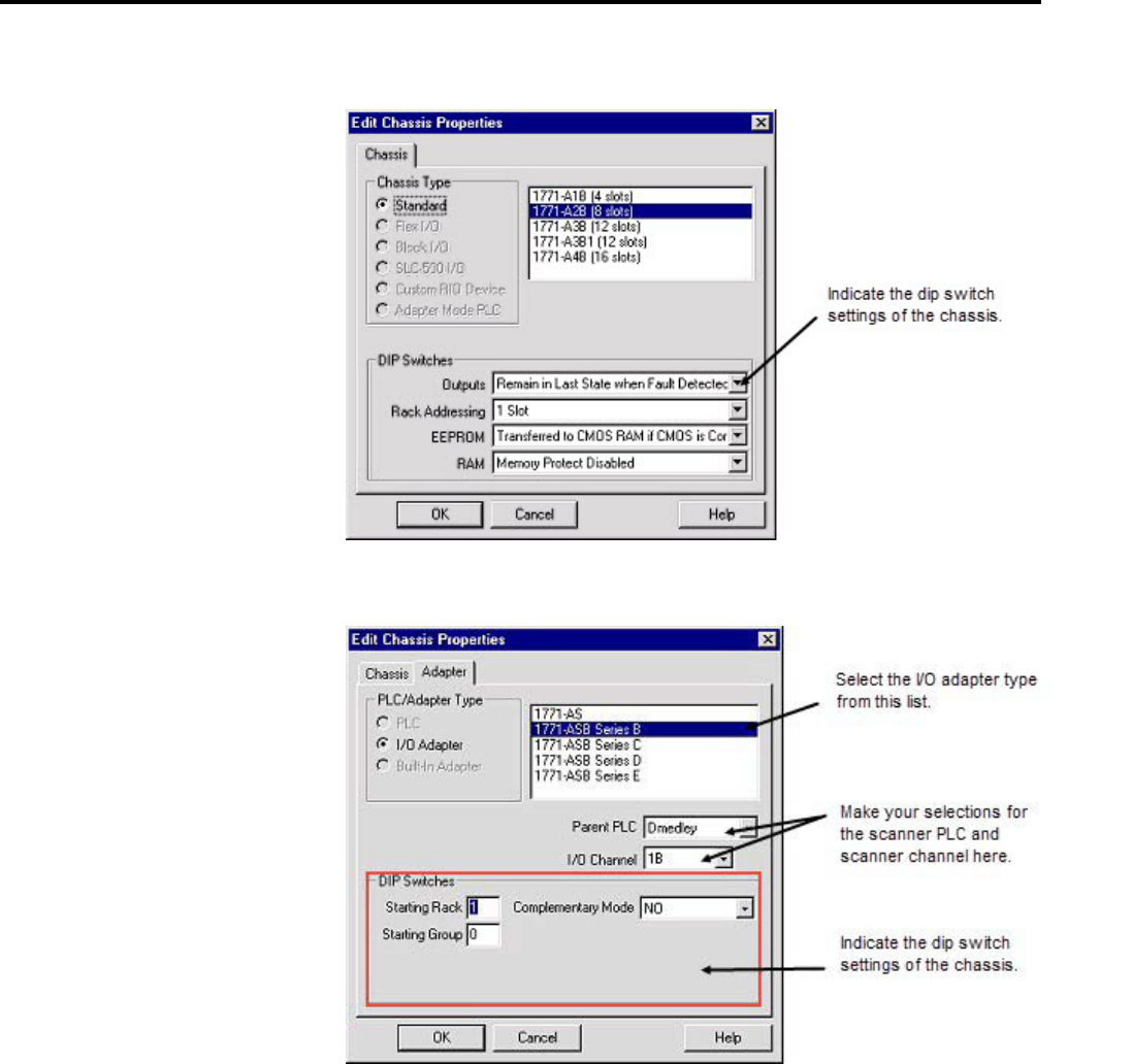
Hardware configuration
Chapter 4
Rockwell Automation Publication - LG5-GR002E-EN-P - December 2019 65
For a PLC-5
For an I/O adapter
To add a module to a chassis
1. Double-click the I/O Configuration icon in the project tree to open the
Chassis table.
Adding I/O modules
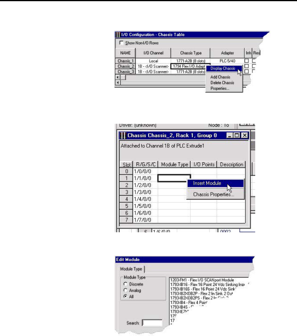
Chapter 4
Hardware configuration
66 Rockwell Automation Publication - LG5-GR002E-EN-P - December 2019
2. Right-click the chassis and select Display Chassis.
3. Right-click the cell for the slot you wish to add a module to and select
Insert Module.
4. Select the module type and the specific module. Click OK.
Using the method above, you can add, delete, or edit modules as well as create
descriptions for each one. Some modules require configuration after they are
added.
Remember that you can always press [F1] for help about any task you are
attempting as you progress through the dialog boxes while you use RSLogix 5.

Hardware configuration
Chapter 4
Rockwell Automation Publication - LG5-GR002E-EN-P - December 2019 67
To configure an I/O module
1. Double-click the IO Configuration icon in the project tree.
2. Right-click the chassis containing the module you want to configure and
select Display Chassis.
3. Right-click the module that you want to configure and select Display
Module. The module configuration window varies from module to module
and configuration is different for discrete and analog modules. Press [F1] to
display help on that particular module.
• Discrete. These modules require no configuration, but symbols,
descriptions, values, and forcing can be assigned to individual I/O
points. Click Close when finished editing.
• Analog. Most analog modules require configuration. These
configurable analog I/O modules are known as "intelligent
block-transfer" modules. In addition to defining block transfer
read/write pairs, configuration parameters must be defined, such as
scaling, alarm limits, or other types of items particular to the specific
type of module.
The first time you edit a particular analog I/O module, the Enter
Module Addresses dialog box appears. Enter addresses or click
Auto-Pick to have RSLogix 5 automatically select the addresses
required for the module, and then click Done. (Auto-Pick is not
available for ControlNet modules.) That module's configuration
window appears. Make your changes, click Accept Edits, then click
Close.
If you want to edit addresses in the future, right-click in the spreadsheet
portion of the module's configuration dialog box and select Edit
Variable Addresses.
Tip:
Most analog modules require block transfer rungs. RSLogix 5 can automatically
generate these rungs for you. On that module's configuration dialog box, click the
Insert Ladder Rungs button.
Configuring I/O

Rockwell Automation Publication - LG5-GR002E-EN-P - December 2019 69
Chapter 5
Importing or exporting the documentation
database
The import and export utilities are available from the Tools menu by clicking
Database. Use the import functionality in RSLogix 5 when you want to apply
documentation that already exists to a project you are currently developing in
RSLogix 5. Use the export functionality in RSLogix 5 to make the database
documentation that is part of your current RSLogix 5 project available to other
projects.
You can apply documentation to newly created logic files by importing existing
database documentation. The existing documentation might come from:
• Projects developed using Rockwell Software’s DOS-based PLC-5 A.I. Series
or 6200 Series programming software
• Another project developed using RSLogix 5
• A spreadsheet application, like Microsoft Excel (saved as a .CSV file)
• An ASCII text file
Sometimes when you import a documentation database, there may be conflicting
entries in the import file and the database. This is called a collision. Before you
begin any import, you can select if you want the imported database instance or the
current database instance discarded if collisions occur.
To import a PLC-5 A.I. Series database
1. Select Tools > Database > Native Import.
2. Click AI.
3. Select which database components to import.
• Address symbols and descriptions (.DSC files)
• Page titles and rung descriptions (.RPD files)
4. Select an option for handling collisions and click OK.
5. Locate and select the database file you want to import and click Open.
Import database
PLC-5 A.I. Series project
documentation database

Chapter 5
Importing or exporting the documentation database
70 Rockwell Automation Publication - LG5-GR002E-EN-P - December 2019
If you have a database that was exported from PLC-5 A.I. Series software,
youmay need to follow the instructions for importing a CSV or ASCII file,
depending on what selections were made when exporting from A.I. If
exported in .CSV, then follow the instructions for importing a .CSV file
on
page 71. If exported in .EAS format, follow the instructions for importing
an ASCII file on page 71.
To import a 6200 Series database
1. Select Tools > Database > Native Import.
2. Click AB 6200.
3. Select which database components to import.
• Address symbols and descriptions
• Instruction comments
• Page titles and rung descriptions
4. Select an option for handling collisions and click OK.
5. Locate and select the database file you want to import and click Open.
By default the file type selected for import is .OP$. The .OP$ file is the
database control file. It references individual database files (for example the
symbol / description file or the page title / rung description file) that reside
in the same folder as the .OP$ file. After an import completes, RSLogix 5
creates a log file that informs you which database files successfully imported
and which database files contained errors and could not successfully be
imported.
To import an RSLogix 5 database
1. Select Tools > Database > Native Import.
2. Click RSLogix 5.
3. Select which database components to import.
6200 Series PLC-5 project
documentation database
RSLogix 5 documentation
database

Importing or exporting the documentation database
Chapter 5
Rockwell Automation Publication - LG5-GR002E-EN-P - December 2019 71
• Address symbols and descriptions
• Instruction comments
• Page titles and rung descriptions
• Symbol groups
4. Select an option for handling collisions and click OK.
5. Locate and select the database file you want to import and click Open.
By default the file type selected for import is .CTD. The .CTD file is the
database control file. It references individual database files (for example the
symbol / description file or the page title / rung description file) that reside
in the same folder as the .CTD file. After an import completes, RSLogix 5
creates a log file that informs you which database files successfully imported
and which database files contained errors and could not successfully be
imported. For a complete list of RSLogix 5 file extensions for individual
database documentation refer to the online help and search "file extensions."
You may wish to import files created with a spreadsheet application such as
Microsoft Excel or files exported from PLC-5 A.I. Series software in .CSV format.
To import a CSV file
1. Select Tools > Database > ASCII Import.
2. Click CSV.
3. Select which database components to import.
• Address symbols and descriptions
• Instruction comments
• Symbol groups
4. Select an option for handling collisions and click OK.
5. Locate and select the database file you want to import and click Open.
For an example of a .CSV file, refer to the online help and search the index for
"CSV format for database import / export."
You can import documentation files that were created using RSLogix 5 software
or PLC-5 A.I. Series software and exported and saved as ASCII delimited files
(.EAS in A.I.). ASCII delimited means that the fields for each RSLogix 5 database
record are enclosed in quote marks and separated by commas.
CSV (Comma Separated Values)
file
ASCII delimited text file

Chapter 5
Importing or exporting the documentation database
72 Rockwell Automation Publication - LG5-GR002E-EN-P - December 2019
To import an ASCII database file
1. Select Tools > Database > ASCII Import.
2. Click RSLogix 5.
3. Select which database components to import.
• Address symbols and descriptions (.EAS files)
• Instruction comments (.EIC files)
• Page titles and rung descriptions (.ERP files)
• Symbol groups (.ESG files)
4. Select an option for handling collisions and click OK.
5. Locate and select the database file you want to import and click Open.
Any file extension may be used for an ASCII delimited text file. You can
look for and select any file extension, not just those listed above.
An example of each of the above files, with an explanation of the data fields
contained within the file, can be found under RSLogix 5
ASCII delimited text file
examples on page 73.
Use the export functionality in RSLogix 5 to make the database documentation
that is part of your current RSLogix 5 project available to other projects.
To export a database
1. Select Tools > Database > ASCII Export.
2. Click the tab for the desired output format: RSLogix 5 A.I., AB 6200, or
CSV (comma separated value).
3. Select which database components to export and specify the filename(s).
Click Help for more information about any of the options on the dialog
box.
4. When exporting the documentation database to A.I. or AB 6200 formats
the symbols, descriptions, and instruction comments may be truncated due
to size restrictions imposed by the PLC-5 A.I. and 6200 Series databases.
This may result in conflicts in the exported data. So, unless you have
accounted for differences between description lengths in RSLogix 5 and
PLC-5 A.I. Series programming software and planned your description text
accordingly, select Treat Source Description as 1 80-character line.
Export database

Importing or exporting the documentation database
Chapter 5
Rockwell Automation Publication - LG5-GR002E-EN-P - December 2019 73
After it has been exported, you can edit the ASCII file with a text editor, or load
the file into another database.
The examples in this section show how the documentation would be represented
in an exported ASCII text file using the RSLogix 5 output format.
Each field in a line of ASCII text is enclosed by quotes and separated by a comma.
Empty fields are represented with quotes with nothing between them.
"B3/0","0","SYMBOL","description","","","","","0","","","0","GROUP_NAME"
ASCII Field # Maximum Length Contents
1 39 characters Address
2 N/A Scope (0=global, 2-255=local program file number
3 20 characters Symbol
4 20 characters Description line 1
5 20 characters Description line 2
6 20 characters Description line 3
7 20 characters Description line 4
8 20 characters Description line 5
9 12 characters Device code (always 0 for addresses that are not real I/O)
10 9 characters Device description above
11 9 characters Device description below
12 N/A Disable cross-reference flag (0=enabled, 1=disabled)
13 20 characters Symbol group name
"RUNG000002-000002","page title","rung comment\"
ASCII Field # Maximum Length Contents
1 39 characters Data table address or rung identifier
2 80 characters Page title
3 64K Rung description
"B3/0","XIC","instruction comment","","","",""
RSLogix 5 ASCII delimited text
file examples
Address symbols and descriptions
(.EAS files)
Page title and rung descriptions
(.ERP files)
Instruction comments (.EIC files)

Chapter 5
Importing or exporting the documentation database
74 Rockwell Automation Publication - LG5-GR002E-EN-P - December 2019
ASCII Field # Maximum Length Contents
1 39 characters Address
2 3 characters Instruction type
3 20 characters Comment line 1
4 20 characters Comment line 2
5 20 characters Comment line 3
6 20 characters Comment line 4
7 20 characters Comment line 5
"GROUP_NAME","description"
ASCII Field # Maximum Length Contents
1 20 characters Symbol group name
2 80 characters Symbol group description
These examples show how a line might appear in an ASCII text file exported using
the A.I. output format. Each field in a line of ASCII text is enclosed by quotes and
separated by a comma.
"B3/0","0","SYMBOL","description","","","","","0","","","0"
The field breakdown of A.I. ASCII delimited text is the same as shown for
RSLogix 5 ASCII output format, except the symbol and description fields are
limited to 15 characters and there is no symbol group field.
"RUNG002-0002","page title","rung comment\"
The field breakdown of A.I. ASCII delimited text is the same as shown for
RSLogix 5 ASCII output format.
AB 6200 documentation database files saved to ASCII text format contain
keywords. Keywords tell the software whether the information immediately
following the keyword is a rung comment, an instruction comment, an address
comment, or a symbol. Some examples are shown below.
SYM B3/0 SYMBOL
SYM O:17/03 UPLOAD
AC B3/0 "description"
AC I:21/03 "AIR STOP CLOSED LIMIT SWITCH\"
Symbol groups (.ESG files)
A.I. ASCII delimited text file
examples
Address symbols and descriptions
(.EAS files)
Page title and rung descriptions
(.ERP files)
AB 6200 ASCII delimited text
file

Importing or exporting the documentation database
Chapter 5
Rockwell Automation Publication - LG5-GR002E-EN-P - December 2019 75
IC XIC N7:10/0 "Surge Tank High Level Alarm"
RC CTD C5:0 " (carriage return)
This is an example of a rung comment with quotation\ marks
and carriage returns at the beginning and end.
" (carriage return)
The key words used in AB 6200 documentation database files are:
SYM – symbol
AC – address comment (description)
IC – instruction comment
RC – rung comment
FCN – SFC name
FCI – SFC comment
IOS – I / O module symbol
IOA – I / O module address comment
IOC – I / O module configuration information
Search "CSV format for database import / export" in the RSLogix 5 online help
index for complete details.
Key Words
CSV (Comma Separated Values)
format

Rockwell Automation Publication - LG5-GR002E-EN-P - December 2019 77
Chapter 6
More about entering ladder logic
This chapter provides information that you can use to make editing your ladder
logic easier.
Tip:
Shortcut methods exist for most editing functions within RSLogix 5. A list of hot
keys (keyboard shortcuts) that enable you to maneuver the software without a
mouse can be found in a help file that you can print out. To access this file, click the
Help folder in the project tree, and then double click on Using the Keyboard.
A.I Series dot commands are now supported by RSLogix 5. To access A.I. Command
Portal Emulation, press [Alt.]. Type the letters of the dot command (such as EI to
insert a rung) and press [Enter]. For more information see Dot commands on
page
80.
Remember to back up your work as you develop your ladder logic programs.
RSLogix 5 uses two types of backup functions that you can access at any time, and
provides you with an auto-recovery file in the case of a power failure. All of these
files contain the entire description database associated with the project.
• Auto-Backup files are created automatically each time you save a project.
To preset how many backups should be retained for any project, select
Tools > Options and click the Preferences tab. Enter a number in the
Number of Backups field.
Auto-backup files (saved as .RSP files) have the letters BAK and a series of
numbers (000 to 999) appended to the filename. For example, an
auto-backup created for project TEST.RSP might be identified as
TEST_BAK000.RSP, and a more recent backup might be identified as
TEST_BAK001.RSP.
• Compressed Format Backup files are typically generated for archiving or
giving to another user. Compressed format backup files include the .RSP
and all database files for the project compressed into a single .RP1 file. Any
auto-backup files that may be included in the project folder are not included
in the compressed backup. To generate a compressed-format backup file,
select File > Backup Project.
To restore an auto-backup file or a compressed format backup file, simply select
File > Open and open the .RSP backup file or the .RP1 file.
Backing up your work

Chapter 6
More about entering ladder logic
78 Rockwell Automation Publication - LG5-GR002E-EN-P - December 2019
If you experience a power interruption, RSLogix 5 provides you with a recent
backup file containing current edits.
RSLogix 5 automatically background saves your project while you are working
with it. (Go to Tools > Options, Preferences tab to set the interval at which these
AutoSaves occur.) This auto-generated recovery file (internal RSP file) is only
available to you the next time you open a project if you have a system crash or your
power is interrupted. When attempting to open a project after a power failure
RSLogix 5 prompts you with two options.
• You can open the latest AutoSave version of the file. This retains all edits
(with the exception of pending database edits) made up until the time of the
last AutoSave before power failed. Once you save this file it becomes your
working version.
• You can revert to the last saved version of the file. This means that any
editing you may have done between the time you last saved the file and the
time of the system crash will be lost.
Important:
You must have saved or closed the file you are working on at least one
time for the auto-recovery process to work. Therefore, it is good practice to
save the file immediately after beginning a new project. This ensures that
your auto-recovery process can begin properly.
The AutoSave feature of RSLogix does not affect the database, and any
pending changes to the database will not be retained using AutoSave.
RSLogix 5 provides several methods for rapidly entering instructions: Quick Key
Mapping, ASCII editing, and A.I. Series style dot commands.
To make your programming tasks faster, RSLogix 5 lets you map any available
alphabetic key (A-Z) on your computer keyboard to a ladder logic programming
instruction.
Crash recovery
Shortcuts for ladder editing
Quick Key Mapping
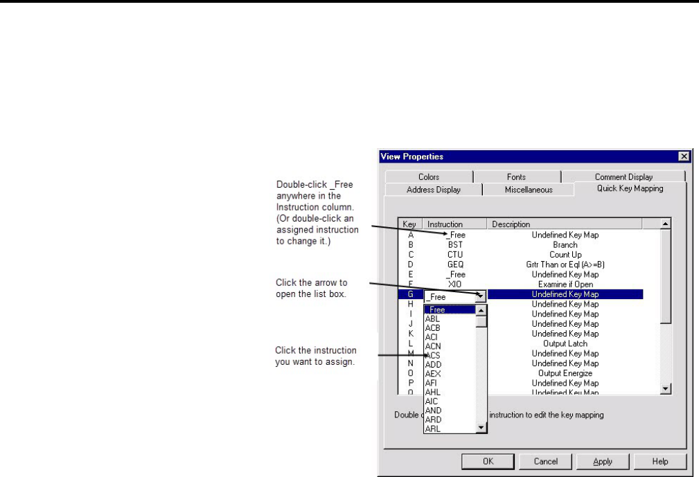
More about entering ladder logic
Chapter 6
Rockwell Automation Publication - LG5-GR002E-EN-P - December 2019 79
To assign quick keys
1. Select View > Properties (make sure you have a program file window
opened and active or you will not be able to select Properties from the
View menu). Click the Quick Key Mapping tab.
2. Double-click _Free anywhere in the Instruction column. (Or double-click
an assigned instruction to change it.)
3. Click the arrow to open the list box.
4. Click the instruction you want to assign.
To use Quick Keys
1. Click a rung number in the ladder window to insert your logic rungs before.
2. Select Edit > Quick Key Mode, or instead press [Ctrl-E] on your keyboard.
This inserts an empty rung into your program and places the software in
Quick Key Mode. Assigned keys are listed at the top of the Ladder View.
3. Type the alphabetic quick keys that you have assigned to instructions. The
instructions will be placed on the rung in the order that you type their quick
key assignments.
4. To exit Quick Key Mode, go to the Edit menu and deselect Quick Key
Mode, or press [Ctrl-E] again.
ASCII Editing is a function of RSLogix 5 that lets you modify instructions using
ASCII editing
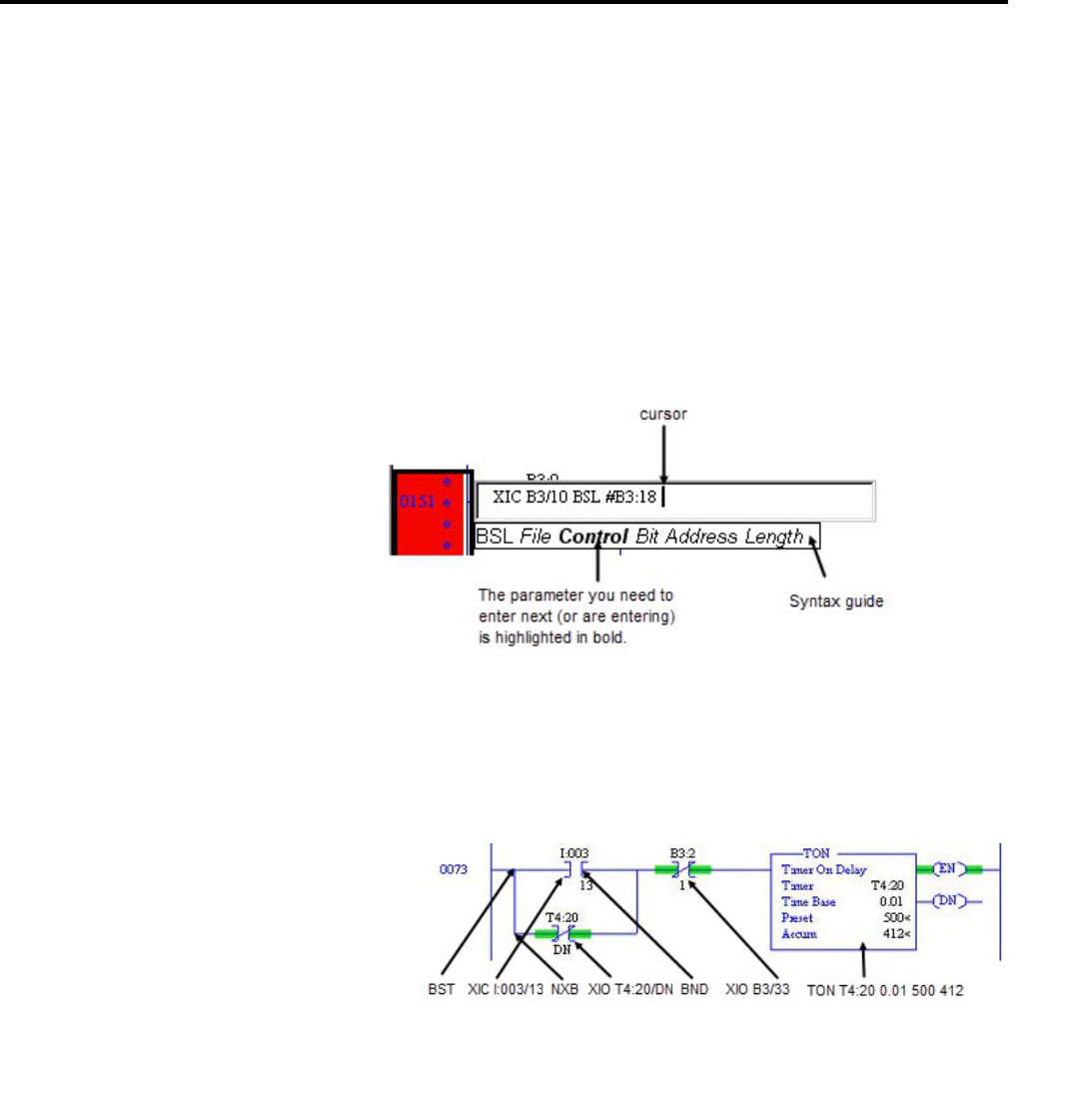
Chapter 6
More about entering ladder logic
80 Rockwell Automation Publication - LG5-GR002E-EN-P - December 2019
ASCII instruction mnemonics instead of having to modify instructions using the
ladder editor.
To edit a rung:
1. Select any instruction on the rung or the rung number and press [/]. Make
sure you press the forward slash key rather than the backslash. You can also
double-click the rung number to open the ASCII box.
2. An ASCII editing box opens. For a rung that already contains logic, the
existing ASCII instructions appear in the box so you can edit them. As you
type an instruction, a syntax guide appears to help you with the parameters.
3. Press [Enter] to accept your edits or you can press [Esc] to discard them.
A sample rung is shown below in both graphical and ASCII format with lines
showing which ASCII mnemonic corresponds to which part of the graphical
rung.
BST=branch start
NXB=next branch
BND=branch end
In A.I. Series software dot commands provided a very rapid means of not only
editing ladder logic, but also accessing various functions of the software such as
Example ASCII rung
Dot commands

More about entering ladder logic
Chapter 6
Rockwell Automation Publication - LG5-GR002E-EN-P - December 2019 81
Advanced Diagnostics search or Who Active. RSLogix 5 emulates the A.I. Series
Command Portal.
To use dot commands in RSLogix 5
1. Press [Alt-.], that is, hold down Alt and press the period.
2. Type in the shortcut command. For example, type
EI (Edit Insert) to insert
a rung.
Tip:
You can combine dot commands with ASCII editing to rapidly enter ladder logic.
Press [Alt - .], type EI, EA, or ER to insert, append, or replace a rung, type a forward
slash ( / ) without a space before it, type the ASCII rung, and press [Enter]. For
example,
EI/XIC I:001/1 OTE O:002/5.
3. Press [Enter].
For a list of dot commands, see online help. Select Help > Contents. Click the
Index tab and type
dot commands. Click Display.
Remember to use the right mouse button to access functionality whenever
possible. The right mouse button provides you with context menus that list
editing options. Keyboard users can press [Shift + F10] to access a right mouse
menu.
Remember that you can press [F1] (or click Help when available) on any
instruction, or within any window to access help. For more information about
online help see Chapter 10, Getting the information you need on page 111
.
You can select multiple rungs by holding down Ctrl and clicking the left mouse
button on every rung you want to select. You can also select a range of rungs by
holding down Shift and clicking the beginning rung and ending rung.
You can jump to any rung in your project by selecting Search > Goto. You can go
to a rung in the current program file or you can go to a rung in another program
file within the same project. You can also press [Ctrl + G] to access the Goto
Rung dialog box.
A list of hot keys (keyboard shortcuts) that enable you to maneuver the software
without a mouse can be found in a help file that you can print out. To access this
file, expand the Help folder in the project tree, and then double-click on Using
The Keyboard.
You can use several different methods to address instructions. You can enter an
address by:
• Manually typing it in
Other shortcuts and tips
Selecting multiple rungs
Jumping to a rung
Keyboard shortcuts
Addressing
Chapter 6
More about entering ladder logic
82 Rockwell Automation Publication - LG5-GR002E-EN-P - December 2019
• Dragging addresses from data files
• Using copy and paste from program to program
Tip:
You can drag-and-drop rungs, branches, instructions, and addresses from file to
file or from the database to a file. To drag-and-drop, position the mouse pointer
over a file element, click and hold down the left mouse button and drag the
element to another location, and then release the mouse button. Red boxes
indicate valid locations; these turn green when properly selected.
Click this button
on the instruction toolbar to place a branch in your ladder
logic. If your cursor is on an instruction, the branch is placed immediately to the
right of the instruction. If your cursor is on the rung number, the branch is placed
first on the rung.
Click on the upper left corner of a branch
and drag to move the entire branch
structure to another location in your ladder logic program. Valid release points
will be visible on the ladder display.
Click the right leg of the branch
, then drag the leg to the right or left. Valid
release points will be visible on the ladder display.
Place the cursor at the upper left corner of a branch leg
, right-click, and select
Append New Branch to place another branch structure within the original
branch structure.
Place the cursor at the bottom left corner of a branch leg
, right-click, and select
Extend Branch Up or Extend Branch Down.
Click on the left edge of the branch leg
you want to copy. In the picture at the
left, this is the center leg. Right-click and select Copy. Finally right-click on a rung
or instruction in your logic and select Paste to insert the rung leg.
Select the right leg of the branch structure
, right-click and select Copy. Finally
click on a rung or instruction in your logic and select Paste from the right mouse
menu to insert the rung structure.
Place the cursor at any location on the branch and click the right mouse button.
Select Delete. If you cut or delete a branch, all instructions on the branch are also
deleted.
The undo button
reverses your last action. You can use this button to walk
through (and undo) your previous actions one at a time. RSLogix 5 remembers up
to 200 previous actions.
Branching
Add a branch
Move a branch
Expand a branch
Nested branches
Parallel branches
Copy branch leg
Copy entire branch structure
Delete a branch
Undo operation

More about entering ladder logic
Chapter 6
Rockwell Automation Publication - LG5-GR002E-EN-P - December 2019 83
If you want to undo a move operation, you must click undo twice. This is because
RSLogix 5 considers a move a series of two actions (copy and cut). You have to let
RSLogix know that you want both the copy and the cut undone. If you click undo
only one time when trying to undo a move, the move appears to be a copy, and you
will see the moved element appear at both locations.
The online editing function lets you monitor and correct your ladder program
when your programming terminal is connected to a PLC-5 processor. Online
editing functions consist of inserting, replacing, and deleting rungs in an existing
ladder program while online with the processor.
While multiple terminals may be simultaneously connected to the same processor,
only one programming device at a time can perform online edits of the program.
The response of other terminals to a processor edit depends on the processor type
and firmware revision. For all Classic and older New Platform PLC-5 processors,
the other terminals will be forced offline and must upload the entire program
again. For later New Platform revisions, the other terminals will remain online
while the changed program file is automatically uploaded in the background.
Within your logic program RSLogix 5 places edit zone markers in the margin to
the left of the left rail. These letters signify edit zones and they indicate the type of
ladder program edit.
Lower case zone markers indicate edits that exist only in the computer memory.
Upper case zone markers indicate edits that exist in the processor memory. After
successfully assembling the edited rungs, the zone markers disappear.
Tip:
You can search for zone markers in your project the same way you might search for
an instruction or an address. Select Search > Find. Click Rung Zones and select
the type of edit zone you want to search for.
Lower-case zone markers Description
e (Offline and online) These rungs are currently under edit within the computer
RAM. If you are working offline, after a successful program verification the
lower-case e will disappear and the edits will be incorporated into the
program. If you are working online, after accepting the rung, the lower-case e
will be replaced by an upper-case I indicating that the rung is now in the
controller's memory and will be inserted into the program file.
i (Online) These rungs are to be inserted into the program. Rungs marked with
a lower-case i currently exist in the computer memory and will not be entered
into the controller until the rung is accepted. After the rung is accepted, the
lower-case i is replaced by an upper-case I.
Online editing
Lower-case zone markers
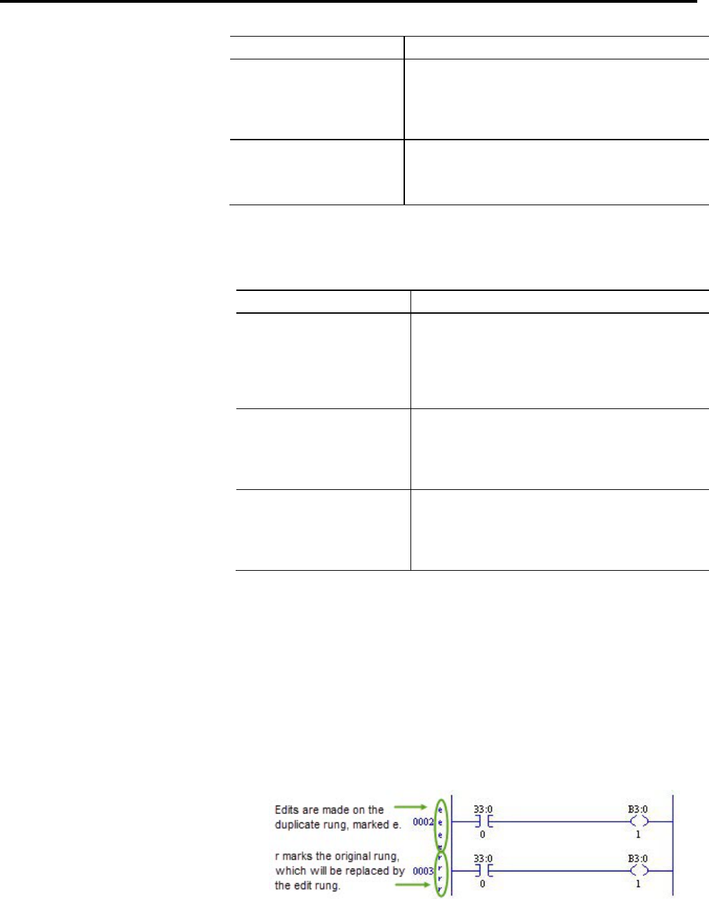
Chapter 6
More about entering ladder logic
84 Rockwell Automation Publication - LG5-GR002E-EN-P - December 2019
Lower-case zone markers Description
r (Online) These rungs are to be replaced in the ladder program. Rungs marked
with a lower-case r currently exist in the computer memory and will not be
entered into the controller until the rung is accepted. An r marked rung is
always preceded by an e marked rung. After the rung is accepted, the
lower-case r will be replaced by an upper-case R.
d (Online) These rungs are to be deleted from the ladder program. Rungs
marked with a lower-case d indicate a deletion reflected in the computer
memory. This deletion will not be reflected in the controller until the rung is
accepted, at which time it will be replaced by an upper-case D.
Upper-case zone markers Description
I
(Online) These rungs have been inserted in the controller's logic program.
You can test the edits by selecting Edit > Online Edits > Test Edits to see
how the rung works in the online ladder program. Click Assemble Edits to
finalize the rung insertion and complete the editing process. (The Test Edits
and Assemble Edits functions are also available by right-clicking on the rung
number.)
R
(Online) These rungs have been replaced in the controller's logic program.
Rungs marked with an upper-case R continue to function in the program
until you select Test Edits to see how the new rung works in the online
program. Select Assemble Edits to finalize the replacement and complete
the editing process.
D
(Online) These rungs have been deleted in the controller's logic program.
Rungs marked with an upper-case D continue to function in the program
until you select Test Edits to see how the program functions without the
rungs in the online program. Select Assemble Edits to finalize the deletion
and complete the editing process.
This example replaces an XIC instruction with an XIO instruction with the same
address while online.
1. Select the rung in the program that requires editing and then select Edit >
Rung Edits > Start Rung Edits or double-click the rung number. A
duplicate of the selected rung (preceded by the e edit zone marker) is shown
in your program, with the original rung marked with r. See the example
below.
Upper-case zone markers
Online editing example
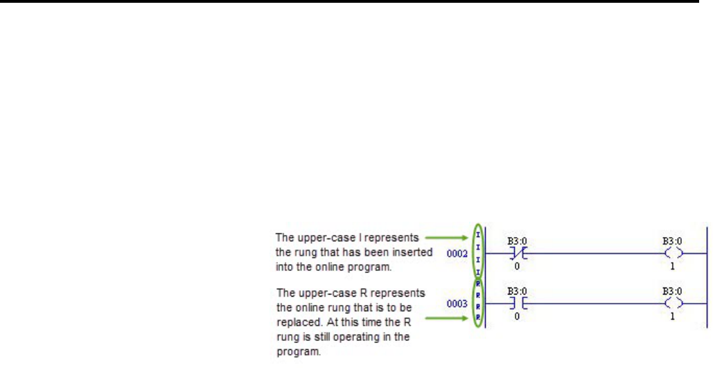
More about entering ladder logic
Chapter 6
Rockwell Automation Publication - LG5-GR002E-EN-P - December 2019 85
2. Make the edits to the rung. The lower-case edit markers do not change since
they represent changes that only exist in the computer memory; these
changes are not yet a part of the online program in the controller. (At this
step you can select Cancel Rung Edits to cancel the edits you have made to
the rung.)
3. Select Edits > Rung Edits > Accept Rung (or right-click the rung number
and select Accept Rung Edits). This changes the edit zone markers and
places both rungs in the controller memory.
At this point you can still right-click the I-marked rung and select Cancel
Edits to cancel the accepted I-marked rung and retain the originally
programmed R-marked rung instead.
4. Select Test Edits. The I-marked rung takes precedence. The program in the
controller will operate with the inserted rung, and the R-marked rung will
be ignored.
5. Select Assemble Edits. All edit zone markers disappear and the edits are
incorporated into the online program. There is no Undo option after online
edits have been assembled.
Going from online to offline with rungs under edit removes the online edits
in RAM. Make sure you have accepted edits before going offline if you want
any changes retained in the processor.
During an online editing session you cannot:
• Resize data table files
• Create or delete program files
• Change program file protection
As many as 16 MCPs can run simultaneously. MCPs may be any mix of ladder
files, SFC files, or structured text files.
To configure MCPs
1. Double-click the S2 data file icon in the project tree.
Online editing restrictions
Configuring MCPs (Main
Control Programs)

Chapter 6
More about entering ladder logic
86 Rockwell Automation Publication - LG5-GR002E-EN-P - December 2019
2. Click the MCP tab. Specify which program files will function as MCPs by
typing their file numbers in the Program File column(s).
3. Click in the check boxes to indicate whether each MCP is to be enabled or
disabled, and whether you want to skip the I/O scan at the end of the
MCP's execution.
Important:
When an MCP is disabled, outputs remain in the state that they were in
during the last scan (that is, all actions remain active). Make sure that you
consider any outputs that might be controlled within that MCP before
disabling it; otherwise injury to personnel or damage to equipment may
result.
You can view scan time data for executing main control programs on the Scan
Times tab of the S2 status file.
A Selectable Timed Interrupt (STI) causes the processor to periodically interrupt
program execution to run an STI program once to completion. Afterwards, the
processor resumes executing the original program file from the point where it was
interrupted.
Select a program file for the STI by double-clicking the Processor Status icon in
the Controller folder in the project tree. Then click the STI tab (you may need to
use the arrow buttons to see more tabs) and enter the information needed to
define the STI. Press Help if you need more information.
A Processor Input Interrupt (PII) specifies when an event-driven input causes the
processor to interrupt program execution and run a PII program once to
completion. After the PII executes, the processor resumes executing the program
file from the point where it was interrupted.
Select a program file for the PII by double-clicking the Processor Status icon in
the Controller folder in the project tree. Then click the PII tab (you may need to
use the arrow buttons to see more tabs) and enter the information needed to
define the PII. Press Help button if you need more information.
Structured text is only supported on Enhanced (New Platform) PLC-5 series C,
revision C and later processors.
Structured text is an English-like set of instructions and mnemonics that you can
use to perform most of the same tasks that you already perform with ladder logic.
The structured text language resembles BASIC and is based on the International
Electrotechnical Commission (IEC) 1131-3 standard for programmable
controller software.
Use structured text as an alternative to, or in conjunction with, ladder logic or
Sequential Function Charts (SFCs). Structured text supports complex expressions
and both logical and symbolic addressing. Use structured text or ladder logic to
program MCPs, subroutines, or actions and / or transitions in SFCs, depending
Configuring Interrupts
STI (Selectable Timed Interrupt)
PII (Processor Input Interrupt)
Using the structured text
editor

More about entering ladder logic
Chapter 6
Rockwell Automation Publication - LG5-GR002E-EN-P - December 2019 87
on which type of programming best suits your application and how much memory
you have available.
To learn more about creating structured text files, click the Help menu in
RSLogix 5, select Contents, and then double-click the Structured Text Editor
book in the Contents tab.
Sequential Function Chart (SFC) programming is a method of programming
complex control systems at a more highly structured level. An SFC program is an
overview of the control system, in which the basic building blocks are entire
program files. Each program file is created using familiar ladder logic. The SFC
approach coordinates large, complicated programming tasks into smaller, more
manageable tasks.
To learn more about creating sequential function chart files, click the Help menu
in RSLogix 5, select Contents, and then double-click the Sequential Function
Chart (SFC) Editor book in the Contents tab.
Using the sequential
function chart (SFC) editor

Rockwell Automation Publication - LG5-GR002E-EN-P - December 2019 89
Chapter 7
More about monitoring data
In addition to allowing you to view changing data by opening multiple data table
windows, RSLogix 5 provides you with several customized methods for
monitoring data.
• Cross Reference
• Forces
• Custom Data Monitor
• Recipe Monitor
• Custom Graphical Monitor
• Histograms
• Trending
The custom data monitor (CDM) file lets you compose lists of addresses that you
monitor frequently, or lists of addresses with interrelated functionality, so that you
can view, document, protect, or even force the changing data values from a single
source file.
When you are online, you can use histograms and trends to see how your program
is behaving over time, by examining bits as the program runs in the PLC-5
processor. A trend logs the data for more than one address (typically related) over
a period of time. Contrast this with a histogram which logs the data contained in a
single address over a period of time.
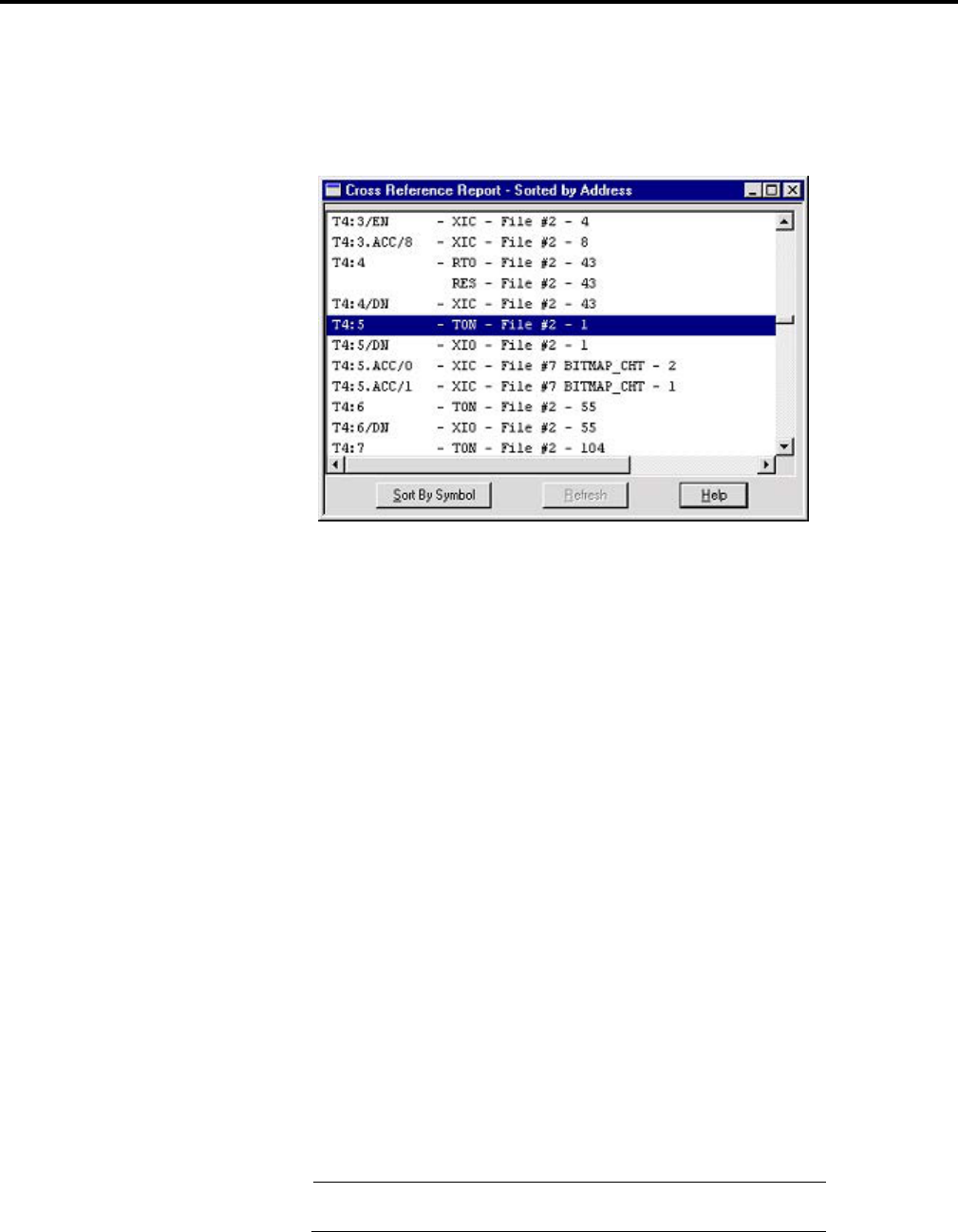
Chapter 7
More about monitoring data
90 Rockwell Automation Publication - LG5-GR002E-EN-P - December 2019
A Cross Reference Report lists all logical addresses in your project and gives the
location of every occurrence of each address. The report includes the following
data: address, symbol, instruction mnemonic, file # (and name), and rung #. You
can sort the Cross Reference Report by symbol or by address.
Display a Cross Reference Report in one of two ways:
• Double-click the Cross Reference icon in the project tree (in the Data Files
folder).
• Right-click an address in your ladder logic and select Cross Reference. The
same report displays, but the address you had selected is highlighted.
As an alternative to a Cross Reference Report, you can choose to display cross
reference information right on the ladder view. To use this feature, select View >
Properties, and click the Address Display tab. Make sure either or both check
boxes are checked in the Cross Reference Display area of the dialog box.
Tip:
You can disable cross references to get online faster. Select Tools > Options. Click
the XRef/Address Wizard tab and uncheck the Enable Cross Reference Online
box.
To monitor forces, double-click the input or output force file in the project tree.
You can also use the Forces dialog box to install and enable or disable forces while
you are monitoring your file offline, or in any processor mode while monitoring
your file online. Use the right-click menu on a bit in the Forces dialog box to force
the bit on or off. For more information about forcing, see the online help.
Important:
All force functions can result in sudden machine movement, possibly
injuring personnel or equipment. Use extreme caution when using forces.
Cross Reference
Forces
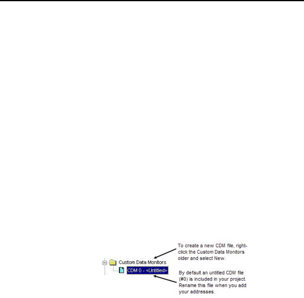
More about monitoring data
Chapter 7
Rockwell Automation Publication - LG5-GR002E-EN-P - December 2019 91
The Custom Data Monitor function can be used to monitor bit addresses and
word addresses.
Addresses in a custom data monitor list can come from any data table file. They do
not have to be from the same data table file.
Features of the custom data monitor include:
• CDM lists can contain any type of address. If you enter the address of a
structure, such as a timer, you can expand it to show all of its members.
• CDM lists can contain ASCII comments to help you clarify bit or word
listings, or annotate the CDM file.
• You can define up to 256 (CDM) lists per project (0-255, inclusive).
• The CDM name is limited to 20 characters.
• The CDM description is limited to 59 characters.
• You can click and drag addresses from the data tables and the ladder logic to
the CDM.
• You can use the [Ctrl] and [Shift] accelerator keys to drag more than one
address at a time from the data tables.
• You can edit address descriptions from the CDM.
To access the Custom Data Monitor feature, double-click the CDM file icon
located in the project tree.
To insert additional addresses or symbols in the monitor list press [Insert]. A new
row will open and you can type in or drag an address from your ladder program or
data table into the empty Address slot. The current value of that address is listed in
the Value column to the right of the address. If a description has been assigned to
that address, it is also displayed.
For more information about using Custom Data Monitor, press [F1] while the
CDM window is active.
The Recipe Monitor is a variation of the Custom Data Monitor. The Recipe
Monitor is used specifically for monitoring groups of related indirect addresses
with a common index.
Custom Data Monitor (CDM)
Recipe Monitor
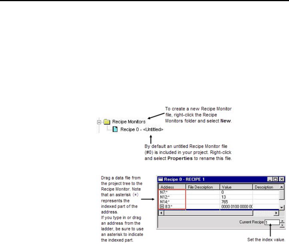
Chapter 7
More about monitoring data
92 Rockwell Automation Publication - LG5-GR002E-EN-P - December 2019
Many PLC projects contain data tables in which each element is relevant for a
different mode of operation. When these data tables are grouped such that
element 1 of each file corresponds to mode 1 of the assembly line used to make
product 1, this is referred to as a "recipe". The easiest way to keep track of recipes is
to use a common reference address with indirect addresses to each of the related
data files. The Recipe Monitor provides an easy and intuitive interface for this type
of application.
To access the Recipe Monitor feature, double-click the Recipe file icon located in
the project tree.
For more information on the Recipe Monitor press [F1] while the Recipe window
is active.
The Custom Graphical Monitor provides the data monitoring of a Custom Data
Monitor, but in an easy to interpret graphical representation. The Custom
Graphical Monitor is a form on which you can place ActiveX® controls for
buttons, sliders, gauges, and charts as well as text and imported images. As is
typical of ActiveX controls, you place and configure controls with the form in
Design mode and switch to Run mode to activate the controls.
Custom Graphical Monitor
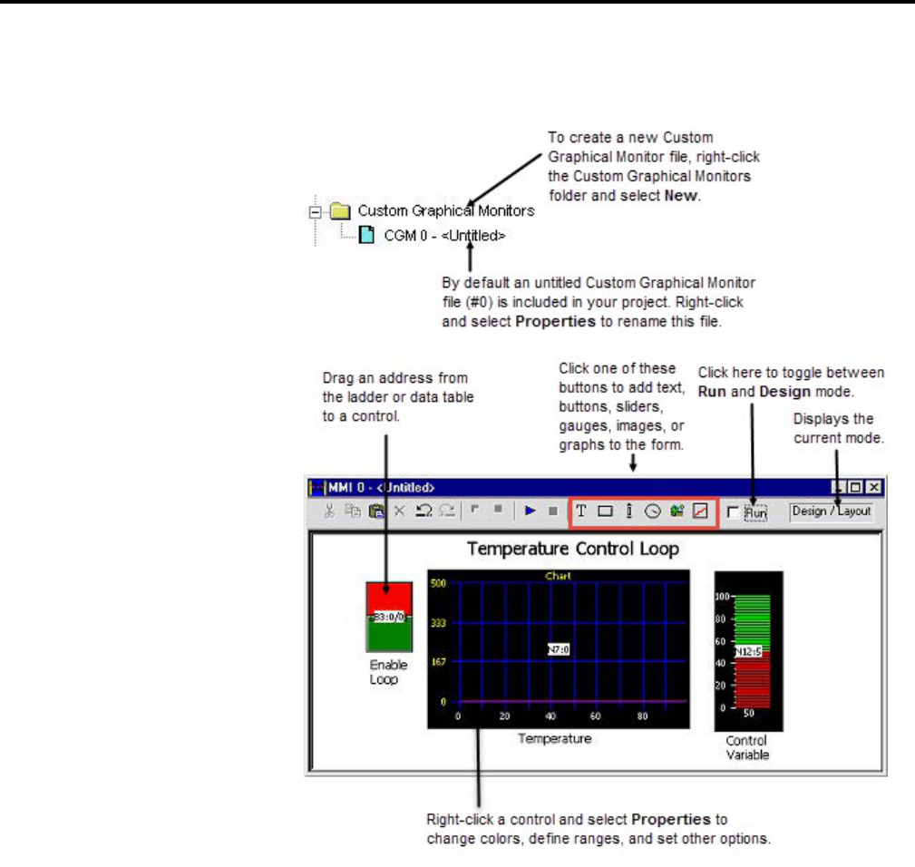
More about monitoring data
Chapter 7
Rockwell Automation Publication - LG5-GR002E-EN-P - December 2019 93
To access the Custom Graphical Monitor feature, double-click the CGI file icon
located in the project tree.
Use the histogram functionality in RSLogix 5 to get information about how an
address's data value changes over time.
Histograms
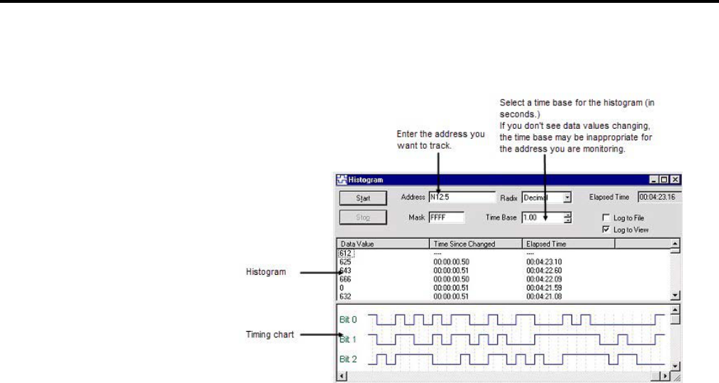
Chapter 7
More about monitoring data
94 Rockwell Automation Publication - LG5-GR002E-EN-P - December 2019
You must be online with the PLC-5 processor to access the histogram function.
Select Comms > Histogram to display the Histogram dialog box.
By clicking Start in this dialog box, the histogram function sends a message to the
PLC-5 processor to begin logging data. Each time the address value changes, the
processor stores the value for the address in a histogram buffer, logging both the
new value and the time interval between value changes. This data is represented in
the top portion of the histogram display window.
If you frequently log certain data, you can save the configuration and simply load it
without having to enter new parameters each time. Use Save Config and Load
Config, accessible from the right mouse menu, for this functionality.
A trend logs the data for more than one address (typically related) over a period of
time. Contrast this with a histogram which logs the data contained in a single
address over a period of time.
This option provides the features of the RSTrendX Viewer plus remote trending
capability. The RSTrendX Viewer is an ActiveX control for displaying process
data in a trend or strip chart recorder format. It is based on the Viewer display in
the RSTrend® Data Acquisition and Trending software.
To create a trend chart
1. Right-click the Trends folder in the project tree and select New.
2. Type a name for your trend chart in the Trend Name field. Then click OK
to create an empty chart. The name can be up to 80 characters in length. An
icon for the new chart appears under the Trends folder in the project tree.
Whenever you want to open the trend chart double-click the icon. Trends
are saved with the project. Logged data is not retained.
Trends
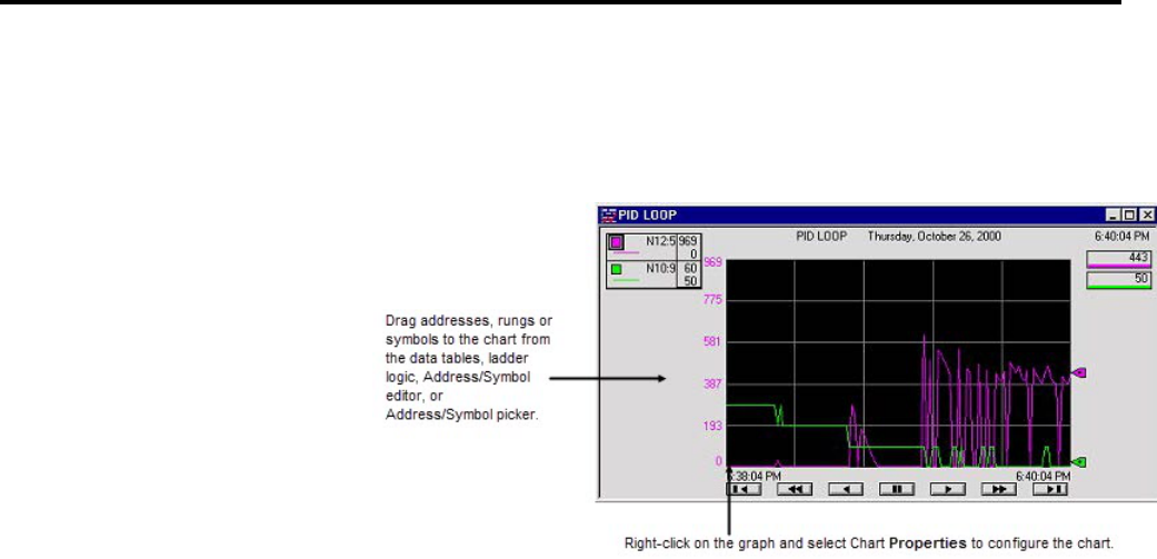
More about monitoring data
Chapter 7
Rockwell Automation Publication - LG5-GR002E-EN-P - December 2019 95
You can create a trend configuration while offline or online. You must be online
to trend data.
The following example shows a Trend for a timer T4:9.
The legend at the left side of the display window contains:
• A colored box representing the pen color. The color can be changed by
double-clicking on the box and then selecting a new color from the available
color chart.
• The symbol name identifying the pen. In the display above, no symbol was
defined for any of the addresses so the address is displayed instead.
• The engineering units if they are defined. N / A means this is currently not
available (not defined) for the selected pen.
Tip:
To access the TrendX help file for more detailed information, right-click on the
chart and select Chart Properties. Click Help. This opens the TrendX help topic
for the Properties General tab. Click Help Topics to browse the TrendX help
table of contents or index.

Rockwell Automation Publication - LG5-GR002E-EN-P - December 2019 97
Chapter 8
Saving and loading processor memory in PC5
libraries
PC5 library files are ASCII text files of the processor memory that contain the
ladder logic, SFC files, structured text, data table files, and force tables. By
exporting (saving to file) and importing (loading into a new project) these PC5
files, you can reuse existing work. PC5 files can be opened in any ASCII text editor
and modified for use in your projects.
• Only verified project data can be saved to a .PC5 file.
• Exported PC5 libraries can contain symbols that are 20 characters in length.
When importing a PC5 library to PLC-5 A.I. Series, symbols will be
truncated to 15 characters. For example, the symbol name
UNLOAD_STRING_INDEX would be truncated as
UNLOAD_STRING_I.
• Graphics characters are not allowed.
• If importing into PLC-5 A.I. Series or 6200 Series software, the name of the
.PC5 file is limited to eight characters. If importing into 6200 Series
software, use only A-Z, 0-9, or the underscore character.
• The file extension of the ASCII processor memory file must be PC5.
• You cannot import or export a CAR (custom application routine) file.
• If you are using passwords and privileges, the privilege configuration
information is encrypted in the exported file to help make unauthorized
access difficult.
• The text editor you use with an ASCII text file must produce only printable
ASCII characters, with no control characters or hidden characters.
You can save entire projects or partial libraries.
To save a library
1. If you want to save a partial library, select the rungs you want to save. For a
full save, skip this step.
2. Either right-click the rungs and select Copy to PC5 Library, or select Edit
> Copy To File.
Things to remember about
library files
Exporting libraries
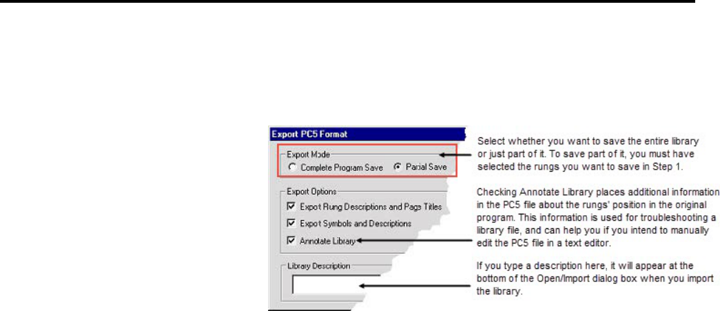
Chapter 8
Saving and loading processor memory in PC5 libraries
98 Rockwell Automation Publication - LG5-GR002E-EN-P - December 2019
3. Supply the path and filename, and click Save.
4. Select the options you want for the export in the Export PC5 Format
dialog box and click OK.
Importing a .PC5 library allows you to reuse existing work by loading portions of
ladder logic that were previously exported, into the current file that you have
opened on your computer. Importing a .PC5 library converts the processor
memory file, previously exported as a .PC5 ASCII file, to the RSLogix 5.RSP
format.
To import a library
1. Open the project into which you want to load the library. If you are loading
a complete program image into an existing project, data table values in the
library will overwrite values in the base program, and incoming rungs will be
appended to existing program files.
2. If you are loading a partial library, select the rung in your program that you
want the library rungs to precede. The library rungs will always be placed
before the rung you select. Data table values from the library will overwrite
existing data table values for those addresses already present in the base
project.
3. Select Edit > Paste From file. (Or right-click a rung and select Paste From
PC5 Library.)
4. On the Open/Import dialog box, select the file you want to import and
click Open.
5. On the Import PC5 Format dialog box you are asked to make some choices
about how you want some of the imported files treated with regard to any
existing documentation and addressing in the current file.
Importing libraries
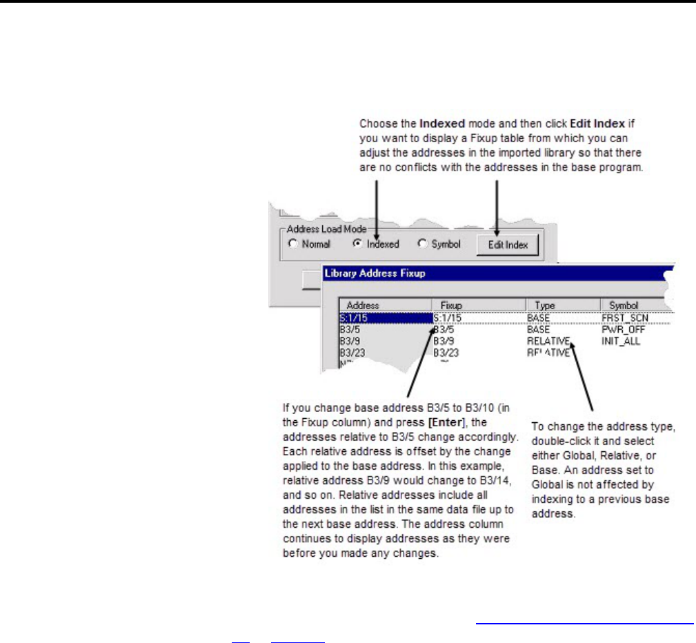
Saving and loading processor memory in PC5 libraries
Chapter 8
Rockwell Automation Publication - LG5-GR002E-EN-P - December 2019 99
6. Choose an Address Load Mode for the library and click OK. Click Help for
more information. See the diagram below for information on the Indexed
mode.
The following sample file is not a complete file. It has been condensed to show a
sampling of each section. Read the section
Creating or editing a PC5 ASCII text
file on page 103 for more information about each section of the library file and
information on comments (text enclosed between percent signs %).
The section identifiers in the left margin are not a part of the file, they have been
included so that you can more easily identify each of the sections in the PC5
library file.
Program Header
START PLC5_40VL SERIES_C REV_C COMPLETE
Data Table
Sample PC5 file

Chapter 8
Saving and loading processor memory in PC5 libraries
100 Rockwell Automation Publication - LG5-GR002E-EN-P - December 2019
DATA O:177
% O:000 % 0X0000 0X0000 0X0010 0X0000 0X0140 0X0000 0X0003 0X0000
% O:010 % 0X0000 0X0000 0X0000 0X0000 0X0000 0X0000 0X0000 0X0000
% O:020 % 0X0000 0X0000 0X0000 0X0000 0X0000 0X0000 0X0000 0X0000
% O:030 % 0X0000 0X0000 0X0000 0X0000 0X0000 0X0000 0X0000 0X0000
DATA I:037
% I:000 % 0X0000 0X0000 0X0000 0X0000 0X0000 0X0000 0X0000 0X0000
% I:010 % 0X0000 0X0000 0X0000 0X0000 0X0000 0X0000 0X0000 0X0000
% I:020 % 0X0000 0X0000 0X0000 0X0000 0X0000 0X0000 0X0000 0X0000
% I:030 % 0X0000 0X0000 0X0000 0X0000 0X0000 0X0000 0X0000 0X0000
..
.
.
Project Name
PROJECT "ICOM5DM7"
2 "MAIN_LADDR"
3 "PID_SUB_RT"
4 "SUB_RT_2"
6 "SUB_RT_4"
7 "BITMAP_CHT"
8 "TREND"
9 "WHEELPROG"
10 "WINVIEW"

Saving and loading processor memory in PC5 libraries
Chapter 8
Rockwell Automation Publication - LG5-GR002E-EN-P - December 2019 101
Program Files
LADDER 2
% Rung: 0 %
SOR XIC B3/0 XIC I:002/1 OTE O:004/0 EOR
% TITLE/RUNG DESCRIPTION ATTACHED TO:RUNG
TITLE:Start Up Diagnostic Check
RUNG DESCRIPTION:
Sample Rung Description
Rung Descriptions can be up to 64K bytes per rung, with 200 lines displayed
The first rung description might explain the program or give useful information
%
% Rung: 1 %
SOR BST XIC I:003/4 NXB XIO T4:5/DN BND XIC B3/10 TON T4:5 1.0
450 315 EOR
% Rung: 2 %
SOR XIO T4:9/DN XIC B3/96 TON T4:9 0.01 150 17 EOR
% Rung: 3 %
SOR LIM 1 T4:9.ACC 40 OTE B3/0 EOR
% Rung: 4 %
SOR XIC T4:3/EN XIC I:003/0 OTE B3/65 EOR
% Rung: 5 %
SOR XIC B3/28 BST OTE B3/88 NXB OTE O:004/6 BND EOR
% Rung: 6 %
SOR BST XIC B3/33 NXB XIO T4:0/DN BND TON T4:0 0.01 500 473 EOR

Chapter 8
Saving and loading processor memory in PC5 libraries
102 Rockwell Automation Publication - LG5-GR002E-EN-P - December 2019
.
.
.
Force Table
FORCE FO:177
% ON OFF %
0X0000 0X0000 % FO:000 %
0X0000 0X0000 % FO:001 %
0X0000 0X0000 % FO:002 %
0X0000 0X0000 % FO:003 %
0X0000 0X0000 % FO:004 %
0X0000 0X0000 % FO:005 %
0X0000 0X0000 % FO:006 %
0X0000 0X0000 % FO:007 %
0X0000 0X0000 % FO:010 %
0X0000 0X0000 % FO:011 %
0X0000 0X0000 % FO:012 %
0X0000 0X0000 % FO:013 %
0X0000 0X0000 % FO:014 %
0X0000 0X0000 % FO:015 %
0X0000 0X0000 % FO:016 %
.
.
.

Saving and loading processor memory in PC5 libraries
Chapter 8
Rockwell Automation Publication - LG5-GR002E-EN-P - December 2019 103
Channel Config
CONFIG $4:2:-1
CONFIG $4:0:347
% $4:0:0 %
-1 -1 26688 7175 18954 7717 -1 -1
26688 7175
% $4:0:10 %
18954 7717 -1 -1 26688 7175
18954 7717 -1 -1
% $4:0:20 %
26688 7175 18954 7717 0 0 0 0 0
0
% $4:0:30 %
0 0 0 0 0 0 0 0 0
0
% $4:0:40 %
0 0 0 0 0 0 0 0 0
0
% $4:0:50 %
0 0 0 0 0 0 0 0 0
0
.
.
.
A PC5 library file contains six sections: program header, data table, project name,
program files, force table, and channel configuration.
Creating or editing a PC5
ASCII text file

Chapter 8
Saving and loading processor memory in PC5 libraries
104 Rockwell Automation Publication - LG5-GR002E-EN-P - December 2019
The first section of a PC5 file is the program header. The program header is a
single line that contains:
• The processor type
• The processor series
• The processor revision
When you perform an export, the program header line contains the word
COMPLETE or PARTIAL. This indicates whether the library contents include a
complete program file or whether a partial library was saved. Every ASCII file
must have a program header section, even if all the remaining sections are empty.
The following program header identifies the processor as a PLC-5 /15 series B
revision A and specifies the library as a complete processor memory file.
START PLC5_15 SERIES_B REV_A COMPLETE
The second section of a PC5 file defines the data table. The data table is the list of
data table files that the processor uses. Files are defined by:
• The word DATA (upper or lower case)
• A letter indicating the file type
• The file number
• The last address defined in the file
Use a separate section for each data table file.
The following data table entry specifies binary file 3 containing 8 words (0-7). The
values on the line following the data table entry specify the data values.
DATA B3:7
0 1 2 3 4 5 6 7
The third section defines the project name and program file names. The project
name is always stored in program file 0.
The following entry specifies DRILL1 as the project name of a processor memory
file and MAIN_LADDR as the name of program file 2. The project name and
program names must be enclosed in quotes and can contain up to 8 characters
(A-Z, 0-9, underscore _ and blank spaces).
PROJECT "DRILL1"
2 "MAIN_LADDR"
Specifying the program header
Specifying the data table
Specifying the project name

Saving and loading processor memory in PC5 libraries
Chapter 8
Rockwell Automation Publication - LG5-GR002E-EN-P - December 2019 105
The fourth section defines the program files. Each program file can contain
sequential function charts, ladder, or structured text programs. Each program file
can have zero or more rungs. Each element and branch in a rung is represented by
a mnemonic along with required data or address information.
The following entry defines ladder program file 3. The word LADDER (upper or
lower case) starts the section with the program file number following. Each line
that starts with an SOR instruction indicates the start of a rung of ladder logic; the
EOR instruction indicates the end of a rung.
LADDER 3
SOR XIO I:030/3 XIC I:030/4 TON T4:10 1.0 32000 0 EOR
SOR XIC I:030/3 MOV T4:10.ACC T4:10.PRE EOR
The fifth section defines the force table. The force table defines inputs and
outputs which are forced into an on or off state. If this section is not included no
forces are applied.
The following force table shows the force status for output address O:057. The
force table is twice the size of the input/output image table.
The force file below is commented. Placing comments, enclosed by percent signs
(%), is for your reference only. They are not imported into the processor or
database.
FORCE FO:057
% ON OFF %
0X0000 0X0000 % FO:000 %
0X0000 0X0000 % FO:001 %
0X0000 0X0000 % FO:002 %
The sixth section defines channel configuration data. This section contains
channel configuration information as well as password and privilege and control
net information. The lengths of each configuration section are variable depending
on the configuration of the channel (i.e. channel zero will have more information
than a DH+ channel).
CONFIG $4:1:411
-1 -1 8224 8224 8224 8224 -1 -1
8224 8224
Specifying the program files
Specifying the force table
Specifying the channel
configuration

Chapter 8
Saving and loading processor memory in PC5 libraries
106 Rockwell Automation Publication - LG5-GR002E-EN-P - December 2019
8224 8224 -1 -1 8224 8224 8224 8224 -1
-1
8224 8224 8224 8224 257 257 -1 0 0
0
0 0 0 0 0 0 0 0 0
0
You can place comments in the PC5 ASCII text file. Comments (text enclosed by
percent signs %) are for your reference only. They are not imported into the
processor or database.
Annotating the PC5 file

Rockwell Automation Publication - LG5-GR002E-EN-P - December 2019 107
Chapter 9
Features in RSLogix 5 Professional
RSLogix 5 comes in two editions: a Standard edition that provides basic ladder
logic editing functions, and a Professional edition that provides additional
functions to expand your automation solutions and make editing ladder logic
simpler. This chapter briefly describes the features included in RSLogix 5
Professional.
RSLogix 5 Professional allows you to expand your automation solutions through
Microsoft Visual Basic for Applications (VBA). VBA allows you add and edit
Visual Basic code within the RSLogix 5 development environment. RSLogix 5
Professional includes an object model that you can access through VBA. VBA
code created through RSLogix 5 Professional is stored in your projects’ .RSP files.
You can run VBA code with RSLogix 5 Standard – to create or edit VBA code you
must use RSLogix 5 Professional.
See the manual titled RSLogix Automation Interface Reference Manual for more
information about using VBA in your automation solutions. This manual is
included with RSLogix 5 Professional.
The Custom Graphical Monitor provides graphical data monitoring for your
projects. In the Custom Graphical Monitor, you can place graphical buttons,
sliders, gauges, charts, text, and imported images.
For more information about using this feature, see Custom Graphical Monitor
on
page 92.
RSLogix 5 Professional allows you to view and edit project databases with
Microsoft Excel software. Microsoft Excel 97 (and later versions) comes with an
ActiveX control that RSLogix 5 can use. You must have Microsoft Excel installed
on the same computer as RSLogix 5 Professional to use this feature.
The Microsoft Excel ActiveX control gives you the powerful editing features of
Excel, such as search/replace, and modifying multiple records at the same time.
Using this control minimizes or eliminates the need for database import/export
operations.
To access the Excel editor, click Tools > Database > Edit Using Excel. The
Address/Symbol Editor will open using Excel as the editing tool.
Microsoft Visual Basic for
Applications support
Custom Graphical Monitor
Editing project databases
using Microsoft Excel

Chapter 9
Features in RSLogix 5 Professional
108 Rockwell Automation Publication - LG5-GR002E-EN-P - December 2019
Pressing [F1] will access the Microsoft Excel Help system.
When the Excel editor is displayed and has focus, RSLogix 5 displays the Excel
menus and toolbars. You can also access Excel functions by using the right-mouse
button menus while working in the editor.
Keep the following information in mind when using Excel to edit the database:
• When you open the Excel editor, the entire contents of the Address/Symbol
database is automatically loaded into the control.
• Changes made within the Excel editor will not be applied to the
Address/Symbol database until you click Apply or OK. When you apply
changes, the entire Address/Symbol database will be overwritten with the
contents of the Excel editor.
• Empty rows within the Excel editor are be ignored when applying the
contents to the database.
• If records are added, removed, or moved within the Excel editor, they will be
sorted when the contents are applied to the Address/Symbol database.
• When you click Apply or OK, all legal records will be written to the
Address/Symbol database. Illegal records (records containing illegal
characters, fields with too many characters, duplicate records, etc.) will not
be written to the database.
• Any errors or illegal records encountered when applying the contents of the
Excel editor to the database will be logged and displayed in a separate
window. You have the option of saving this information to a file.
• If you close the Excel editor without clicking Apply or OK (by clicking
Cancel), the editor closes without overwriting the database. Changes made
in the editor since the last Update Changes operation will be lost.
• The Excel editor is limited to approximately 64,000 rows per sheet.
Databases with more than 50,000 records will have their contents spanned
to multiple Excel sheets.
• All standard features of the Excel ActiveX control will be available to
manipulate the database. When the Excel editor has focus, these features are
accessed through the menus or toolbars or from the right-mouse menu.
Remember, you can always get help with the Excel editor by pressing the
[F1] key.
The Logic Trace feature lets you navigate through your ladder logic like using a
Web browser. As you move your cursor through a ladder logic project, the Logic
Trace feature keeps track of where you have been. You can then use the Logic
Trace toolbar to navigate back to previous positions, or from earlier positions to
later ones.
Logic Trace
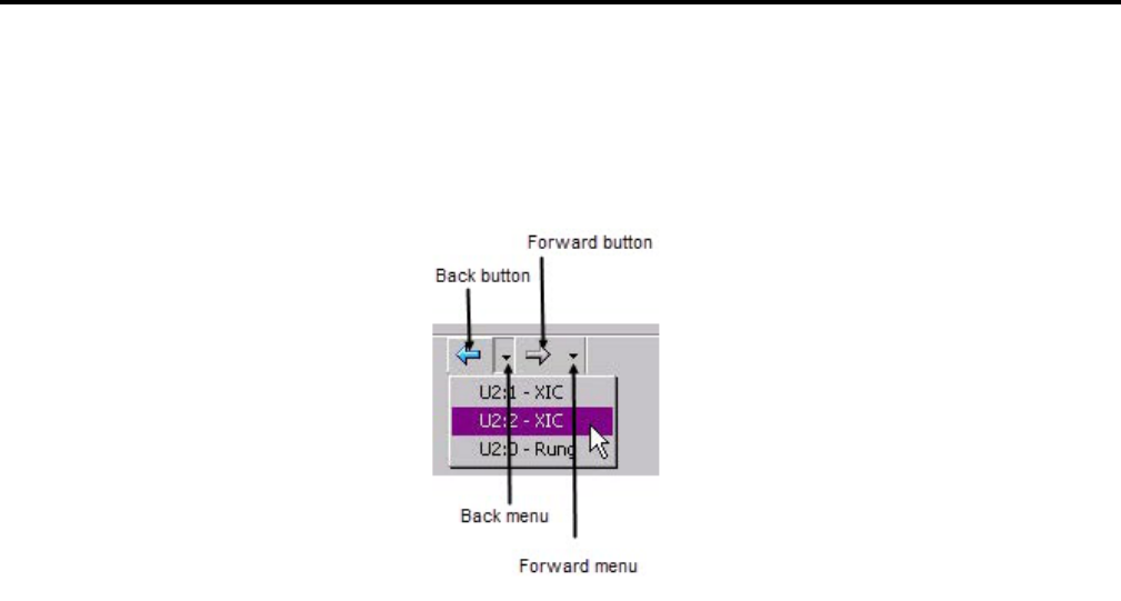
Features in RSLogix 5 Professional
Chapter 9
Rockwell Automation Publication - LG5-GR002E-EN-P - December 2019 109
You can turn the logic trace toolbar on or off by clicking View > Toolbars and
selecting or deselecting the Logic Trace toolbar.
As you move your cursor through the ladder logic, the software records the
positions of your cursor. When no back or forward history is available, the logic
trace arrow buttons are disabled (grayed out).
Actions that create a "back" navigation history include cross reference navigation,
program file display change, clicking your mouse on ladder logic rung/instruction
elements, searching ladder logic, using the Goto Rung function, using dot
commands, etc. Using the keyboard arrow keys will not generate a navigation
history.
Actions that create a "forward" navigation history are limited to clicking an
enabled "back" toolbar button or selecting a location from the "back" pull down
menu.
When you click a "back" button, the cursor will move to the previous location in
the navigation history. Once you have moved backward in the navigation history,
clicking the "forward" button will move the cursor forward through your
navigation history.
The pull down menus are limited to a maximum of 10 entries. Each entry lists a
rung/instruction location. While the menus are limited to showing a maximum of
10 entries, the arrows allow you to go much farther back.
If you delete an instruction or rung that is in the history, that item is removed
from the logic trace navigation history. If you edit a rung or instruction that is in
the navigation history, it remains in the history.
How logic trace works

Chapter 9
Features in RSLogix 5 Professional
110 Rockwell Automation Publication - LG5-GR002E-EN-P - December 2019

Rockwell Automation Publication - LG5-GR002E-EN-P - December 2019 111
Chapter 10
Getting the information you need
Use this chapter to review the sources of additional information on RSLogix 5
software, including online help, RSLogix 5 training, and technical support.
You can find out more information about RSLogix 5 software by consulting:
• RSLogix 5 online help
• RSLogix 5 training
• Technical support services
RSLogix 5 online help provides overviews, a description of the fields on every
dialog box, and step-by-step procedures for working with all of the features of
RSLogix 5. To open online help while running RSLogix 5 you can:
• Click Help on any window
• Press [F1] while the cursor is on any instruction, dialog box, or window
view
• Select Help > Contents
• Expand the Help folder in the project tree and then double-click on any
informative file listed (except for User Application Help which is only
available if you have defined it) to launch a help file.
To display the tabbed help dialog box
• Select Help > Contents and click the appropriate tab or
• Expand the Help folder in the project tree, double-click Contents, and
click the appropriate tab
RSLogix 5 online help
Using the Contents, Index, and
Find tabs
Contents
Chapter 10
Getting the information you need
112 Rockwell Automation Publication - LG5-GR002E-EN-P - December 2019
Tip:
To print a group of help topics, select a book from the Contents tab, and then click
Print. All of the individual topics in that book will print.
The index tab provides a list of guide words or subjects just like the index of a
book. This is a quick way to find information about a specific topic. Follow the
directions on the Index tab.
If you don't see what you are looking for in the contents or index, you can search
the entire help file for all occurrences of a word. Follow the directions on the
dialog box to find a word.
The first time you click the Find tab you will see a message about building a word
list. Follow the directions on the screen. The default selection is generally
sufficient. For more information, see Microsoft's online help (Start > Help).
Click any instruction in your project and press [F1] for help on that instruction.
To pick an instruction from a list instead, select Help > PLC-5 Instruction Help.
From this topic you can also search for an instruction by category.
Sample instructions are shown in the help with parameters entered so you can
more easily determine what information (bit address, constant, etc.) you must
supply.
A list of hot keys (keyboard shortcuts) that enable you to maneuver the software
without a mouse can be found in a help file that you can print out. To access this
file, select Help > Using The Keyboard. To print any of the keyboard help topics,
just click Print at the top of the window.
Index
Find
Instruction set help
Keyboard shortcuts

Getting the information you need
Chapter 10
Rockwell Automation Publication - LG5-GR002E-EN-P - December 2019 113
Some of these keyboard shortcuts (sometimes called Ctrl-key accelerators) are
standard to the Windows operating system and work across all Windows based
products. Other shortcuts will only work with the RSLogix 5 and 500 products.
The User Application Help feature allows you to add your own reference source
(document, web page, etc.) to the RSLogix 5 project. You can use whatever format
you want for the source as long as the computer running RSLogix 5 can open and
read that source. For example, you could use a Microsoft Word doc file, provided
that you had Word on your computer. Or you could use an HTML file provided
that you had a browser that could read the file.
Your User Application Help file is saved with the project in RSLogix 5. You can
specify one User Application Help file per project.
To set up your User Application Help file
1. Create the source file for your User Application Help.
2. From the project tree in RSLogix 5, right-click User Application Help
(under the Help folder) and select Properties. The User Application Help
dialog box appears.
3. Enter the path and file name, or the URL for your source file and click OK.
To specify a different source file, go back to the Properties dialog box and enter
the new path and name.
To display the User Application Help file, double-click on User Application
Help (under the Help folder in the project tree).
User Application Help
Printing a popup help topic
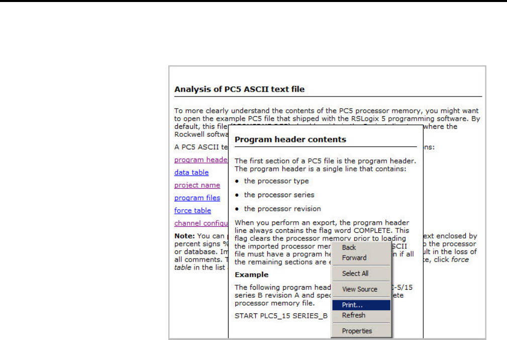
Chapter 10
Getting the information you need
114 Rockwell Automation Publication - LG5-GR002E-EN-P - December 2019
To print the contents of a popup window, right-click in the popup and select
Print Topic.
To learn tips and tricks for getting the most out of the help system, select Help >
Using Help.
Rockwell Software offers both classroom and computer-based training for
RSLogix 5.
One of the best ways to increase your proficiency at using Rockwell Software
products is to attend a Rockwell Software training program. Our training
programs can help you master the basics and show you how to unleash the full
potential of our software.
We offer a wide range of training programs, from regularly scheduled classes
conducted at Rockwell Software facilities, to custom-tailored classes conducted at
your enterprise. The size of each class is kept small intentionally to maximize
student engagement.
For more information about our training programs:
• Visit our web site at www.software.rockwell.com/Training/
• View the Support and Training help file either from Help on the menu
bar or from the Help folder in the project tree.
• Contact the Rockwell Software Training Coordinator at 877-724-7864.
Learning more about using
online help
RSLogix 5 training
Classroom training

Getting the information you need
Chapter 10
Rockwell Automation Publication - LG5-GR002E-EN-P - December 2019 115
A computer-based training program for RSLogix 5 is available for purchase.
Contact your distributor to order RSTrainer 2000 for RSLogix 5. A demo of the
training program is included on the RSLogix 5 CD-ROM. To run the demo,
insert the RSLogix 5 CD-ROM into the CD-ROM drive. When the menu
appears, select Try RSTrainer 2000 for RSLogix 5.
If the CD-ROM does not autorun, open the Start menu and select Run. Type
x:\autoplay (where x is your CD-ROM drive), and click OK. Select Try
RSTrainer 2000 for RSLogix 5 from the menu.
If you cannot find answers to your questions in the Getting Results with RSLogix 5
publication or in the online help, you can call Rockwell Software technical
support.
Telephone—440-646-7800
Fax—440-646-7801
World Wide Web—www.software.rockwell.com/support
Support staff are available Monday to Friday 8 AM to 5 PM EST, CST, MST, and
PST, except during U.S. holidays.
When you call, you should be at the computer running the Rockwell Software
product and be prepared to provide the following information:
• Product serial number on the Activation disk labels (You can find the serial
number online. On the RSLogix 5 menu, click Help, and then click
About.)
• Product version number
• Hardware you are using
• Microsoft Windows operating system and service pack you are using
• Exact wording of any messages that appear on the screen
• Description of what happened, and what you were doing when the problem
occurred
• Description of how you tried to solve the problem.
Interactive training
Technical support services
When you call

Rockwell Automation Publication - LG5-GR002E-EN-P - December 2019 117
Appendix A
EVMOVE Activation
RSLogix 5 software currently supports both the EVMOVE activation and
FactoryTalk Activation systems for activating software. New installations of
RSLogix 5 software must use the FactoryTalk Activation system. Older
installations of RSLogix 5 that have used the EVMOVE activation system may
continue to do so.
Rockwell Software advises all RSLogix 5 users to upgrade their activation system
to avoid problems with future releases of RSLogix 5.
This appendix applies only to the EVMOVE activation system.
Rockwell Software’s products are copy-protected. Only a computer with access to
the activation key can run the software. The key is located in an activation file,
which is originally located on the Master disk supplied with the RSLogix 5
product. The activation file contains one activation key per product. Each key
contains one or more licenses depending on how many copies of the product you
have purchased.
Tip:
Store your Master disk in a safe place. If your activation becomes damaged, the
Master disk may be the only means to run your software in an emergency.
During the setup process, the setup program gives you the opportunity to move
the activation file from the Master disk to the root folder of the drive on which
you’re installing the software.
When you launch RSLogix 5, the software first checks your local hard drives, then
network hard drives, and finally local floppy drives for activation. If the system
fails to detect either the activation file or the Master disk, you will receive an error
message stating that activation is required to run the RSLogix 5 software.
Tip:
Systems attached to extensive networks can take quite a while to search for
activation files on all available drives. You can use the CHECKDRIVES environment
variable to specify and/or limit the drives your software checks for activation files
and to specify the order in which they are checked. Refer to the activation utilities
online help file by selecting Help > Copy Protection.

Appendix A
EVMOVE Activation
118 Rockwell Automation Publication - LG5-GR002E-EN-P - December 2019
To avoid damaging your activation files, do not perform the following
operations with activation files on the hard drive.
• Restore from backup
• Upgrade the operating system
• Compress or uncompress the hard drive
Defragmentation utilities will not harm activation files.
Important:
Certain anti-virus software packages, such as Norton Anti-virus, can
corrupt the activation files. Configure your anti-virus software to avoid
checking the files EVRSI.SYS and 386SWAP.PAR.
Before running any type of utility that may modify the structure or organization of
the hard drive, remove activation from the hard drive:
1. Use the Move Activation utility (EvMove) to move activation files from the
hard drive to an activation disk.
Important:
Do not use the Move Activation utility if Rockwell Software products are
currently running. Ensure all software programs are closed before
initiating the EvMove utility.
Run EVMOVE.EXE from your hard drive (located in C:\Program
Files\Rockwell Software\RSUtil if you accepted the default folder location
during installation).
2. Perform the hard disk operation.
3. Move the activation files back to the hard drive.
Important:
You must use the move utility, EvMove, to move activation files. Attempts
to copy, move or e-mail an activation file by other means will damage the
file.
Depending on your needs, you can activate RSLogix 5 from any of the following:
Hard drive. The activation key resides on your computer’s hard disk. Use this
method if you will typically use RSLogix 5 on only one computer. This is the
default method if you activate RSLogix 5 during installation. To run RSLogix 5 on
a different computer, move the activation key back to the Master disk, and then to
the hard drive of the new computer.
Diskette drive. The activation key resides on a floppy disk (activation disk). Use
this method if you will typically use RSLogix 5 on more than one computer, for
Protecting your activation
files
Activating RSLogix 5

EVMOVE Activation
Appendix A
Rockwell Automation Publication - LG5-GR002E-EN-P - December 2019 119
example, if you want to run RSLogix 5 on a desktop computer at some times and a
portable computer at others.
Network drive. The activation keys reside on a network drive. Use this method if
you have purchased multiple licenses of the software and want several users to be
able to activate the software over a network. Refer to the online help for
instructions on moving activation to a network drive (refer to the "Finding more
information about activation" section in this chapter to access online help).
The utilities for moving and resetting activation are called EvMove and Reset
respectively. Reset is used when an activation file has been damaged. The
EVMOVE.EXE and RESET.EXE files are located on your hard drive (located in
C:\Program Files\Rockwell Software\RSUtil if you accepted the default folder
location during installation). To run these programs, select Start > Progams >
Rockwell Software > Utilities > Move Activation or Reset Activation.
The online help (COPYPROT.HLP) provides more extensive information on
activation including subjects such as:
• KEYDISK. Set this environment variable to tell your computer to look for
activation on floppy drives.
• CHECKDRIVES. Specify which drives to search for activation.
• Network activation. Move activation to a network server to allow multiple
users access to the activation.
• Moving activation. See detailed instructions for moving activation.
• Resetting activation. See detailed instructions for using the Reset utility to
repair a damaged activation file.
• Troubleshooting. Look up error messages, get problem-solving suggestions.
You can access online help:
• From Help on one of the EvMove or Reset dialog boxes.
• From RSLogix 5 by selecting Help > Copy Protection from the main
menu.
• Without running either RSLogix 5 or the activation utilities. From the
Windows Start menu, select Programs > Rockwell Software > Utilities >
Activation Help (if you accepted the default folder location during
installation).
Following are some common problems that people encounter with activation and
their solutions.
Running the activation utilities
Finding more information
about activation
Some common questions

Appendix A
EVMOVE Activation
120 Rockwell Automation Publication - LG5-GR002E-EN-P - December 2019
If you have lost the activation because the activation file is damaged, you need to
reset activation. Follow the Reset Codes instructions on the Rockwell Software
Technical Support web page, or call the technical support telephone number. The
web page and telephone number are both listed on the inside front cover of this
guide.
If you cannot obtain a reset code immediately, follow these instructions to use the
Master disk to activate the software as a temporary solution.
To use the Master disk to activate software
1. Set the KEYDISK environment variable to TRUE. (Please refer to the
online help.)
2. Insert your Master disk in the floppy drive.
3. Run your software as usual. Your software will find the activation on the
Master disk.
No. Deleting the program files does not delete your activation. The activation files
are not stored in the program folder; they are located in the root folder. Your
activation files will not be lost unless you format the hard drive, tamper with
hidden files in the root folder, or perform certain other hard drive operations (For
more information, see "Protecting your activation files" section in this chapter).
To get the software running again, simply reinstall the software, but do not move
the activation when given the opportunity.
It has to do with a disk modification that NT does not allow. If you have access to
a Windows 98 machine, you can create a disk that will work under NT. Format a
floppy and move any activation file to it under Windows 98. (You can move the
activation back off the disk if you want to keep it where it was.) Then take that
disk to your Windows NT machine and move the activation to it.
My activation files were
damaged. What should I do?
I accidentally deleted the
software folder on my hard
drive. Do I need to call Rockwell
Software for replacement
activation files?
Why can’t I move activation to a
new floppy disk on a Windows
NT system?

Rockwell Automation Publication - LG5-GR002E-EN-P - December 2019 121
6
6200 Series software
import database 72
opening project in RSLogix 5 63
problems importing to RSLogix 5 64
A
A.I. Series software
dot commands 82
import database 71
opening project in RSLogix 5 63
accept rung edits 86
actions 36
activation 16, 119
concurrent 20
damaged 122
EVMOVE 16, 19
FactoryTalk Activation 16
FactoryTalk Activation Client 19
file 119
key 119
moving 122
network 121
node-locked 20
resetting 121
troubleshooting 121
utilities 121
activation file
definition 11
addressing methods 83
anti-virus software 120
archive
definition 11
ASCII database files 74, 76
importing 73
ASCII editing 81
assemble edits 86
auto-backup 79
AutoSave 80
B
back up 79
definition 11
backup files 79
branching 84
add a branch 84
copy branch leg 84
copy entire branch structure 84
delete branches 84
expand a branch left or right 84
move a branch 84
nested branches 84
parallel branches 84
C
calling Rockwell Software 117
cancel rung edits 86
CDM 93
channel configuration 57
chassis
adding 67
changing 65
chassis configuration 53
chassis table 65
CHECKDRIVES 119, 121
close a program file 47
collisions in database import 71
communication channels 57
communications
configuring 51
system 51
communications driver 48
configuring 48
compressing the hard drive 120
concurrent activation 20
configure
adapter 66
analog I/O 69
chassis 65
chassis and I/O 53
communication channels 57
discrete I/O 69
MCP 88
PII 88
processor 66
STI 88
system communications 51
controller communications 58
Index

Index
122 Rockwell Automation Publication - LG5-GR002E-EN-P - December 2019
ControlNet 53
copy protection, see activation 16, 119
crash recovery 80
create
data table file 54
new project 52
program file 54
CSV files
importing 73
CTD files 72
custom data monitor 93
custom graphical monitor 94, 109
D
d in rung margin 85
D in rung margin 86
data monitoring methods 91
data table files
creating 54
monitoring 58
database
adding documentation 56
exporting 74
import from A.I. 63
importing 71
database editor
accessing 56
defined 56
defragmentation utilities 120
delete
branch 84
deleting the software folder 122
disk space required 15
document conventions 11
documentation database
editing with Excel 109
documentation, see database 56
dot commands 82
download 58
definition 11
drag and drop 83
driver 48
configuring 48
DSC files 71
E
e in rung margin 85
EAS file format 75
editing
database with Excel 109
editing while online 86
EIC file format 75
entering ladder logic 54
ERP file format 75
error messages 119
ESG file format 76
EvMove 120
EVMOVE activation 16, 19
Excel
using to edit project databases 109
exporting
database files 74
PC5 libraries 99
F
FactoryTalk Activation 16
FactoryTalk Activation Client 19
FactoryTalk Activation Tool 19
FactoryTalk Activation Wizard 19
FactoryTalk Administration Console 18
FactoryTalk Directory Configuration Wizard 18
FactoryTalk Local Directory 18
FactoryTalk Network Directory 18
FactoryTalk ServicesPlatform 18
features of RSLogix 5 45
files
CSV 73
CTD 72
data table monitoring 58
DSC 71
EAS 73
EIC 73
ERP 73
ESG 73
new data table file 54
new program file 54
new project 52
OP$ 72
OP$ files 64
open A.I. or 6200 63

Index
Rockwell Automation Publication - LG5-GR002E-EN-P - December 2019 123
open multiple programs 47
open project 53
opening 6200 files 64
RPD 71
find 59
forces, monitoring 92
G
glossary 11
go online 58
go to rung 83
H
hardware configuration 65
hardware requirements 15
help
adding your own help document 115
online 11, 113
see also online help 113
histograms 95
difference from trends 91
hot keys 83, 114
I
i in rung margin 85
I in rung margin 86
I/O configuration 53
I/O modules
adding 67
importing
A.I. and 6200 Series files 63
A.I. database 63
database files 71
PC5 libraries 100
installing
RSLinx Classic Lite 17
RSLogix 500 17
Security Server Client 20
instruction toolbar 45
instructions
help using 114
quick entry 80
K
keyboard shortcuts 83, 114
KEYDISK 121
L
ladder editor 54
ladder logic program 54
ladder view 45
laptop considerations 58
letters in left margin 85
libraries 99
libraries, definition 11
lists of bit and word addresses 93
local directory 18
logic trace 110
M
main control programs 88
master disk 119
MCP 88
menu bar 45
mnemonic, definition 11
monitoring data 58, 109
cross reference 92
custom data monitor 93
custom graphical monitor 94
forces 92
histograms 95
recipe monitor 94
trends 96
moving
activation 122
addresses 83
instructions 83
N
network
activation 121
network directory 18
node-locked activation 20

Index
124 Rockwell Automation Publication - LG5-GR002E-EN-P - December 2019
O
online bar 45
online editing 85
example 86
restrictions 87
zone markers 85
online help 113
contents 113
find 113
index 113
instruction set 114
print popup 115
print several topics 113
Online Now 61
OP$ files 72
open
existing projects 53
more than one project 48
program files 47
P
partial download 58
PC5 libraries
annotating 108
channel config portion of ASCII file 107
data table portion of ASCII file 106
editing ASCII text file 106
exporting 99
force table portion of ASCII file 107
importing 100
program files portion of ASCII file 107
program header portion of ASCII file 106
project name portion of ASCII file 106
rules about libraries 99
sample ASCII file 101
PII( processor input interrupt) 88
policies 34
printing a report 60
processor input interrupt 88
program files
creating 54
open multiple 47
project tree
about 45
projects
creating new 52
definition 11
open A.I. or 6200 file 63
open existing 53
Q
quick key mapping 80
quick start steps
for development 48
for maintenance 61
R
r in rung margin 85
R in rung margin 86
recipe monitor 94
recover after power loss 80
replace 59
reports
preview 60
printing 60
resetting activation 121
restoring from backup 120
results window 45, 56
RPD files 71
RSAssetSecurity 17, 18
importing database from Security Server 30
RSLinx Classic
configuring driver in 48
version required 15
RSLinx Classic Lite
installing 17
RSWho 48
rungs
copy and paste 83
go to 83
selecting multiple 83
S
search 59
secured actions 36
security policies 34
Security Server
importing database into RSAssetSecurity 30
Security Server Client

Index
Rockwell Automation Publication - LG5-GR002E-EN-P - December 2019 125
installing 20
selectable timed interrupt 88
sequential function charts 89
SFC editor 89
shortcuts 83
ASCII editing 81
dot commands 82
keyboard 83
quick key mapping 80
software requirements 15
standard toolbar 45
start rung edits 86
status bar 45
STI(selectable timed interrupt) 88
structured text 89
system communications
configuring 51
T
technical support services 117
terms 11
test edits 86
timing chart 95
toolbars
add-in 45
instruction 45
logic trace 110
main 45
menu bar 45
online bar 45
standard 45
tracing logic 110
training 116
classroom 116
computer-based 116
trends 96
difference from histograms 91
troubleshooting 43
activation 121
U
uncompressing the hard drive 120
undo 84
upgrading the operating system 120
upload, definition 11
user application help 115
V
VBA 109
verification, definition 11
verify program logic 56
Visual Basic for Applications support 109
W
Windows
98 122
NT 122
X
x-ref 92
Z
zone markers 85
zone, definition 11
Rockwell Automation maintains current product environmental information on its website at http://www.rockwellautomation.com/rockwellautomation/about-us/sustainability-ethics/product-environmental-compliance.page.
Allen-Bradley, Rockwell Automation, and Rockwell Software are trademarks of Rockwell Automation, Inc.
Trademarks not belonging to Rockwell Automation are property of their respective companies.
Rockwell Automation Publication - LG5-GR002E-EN-P - December 2019
Rockwell Automation Publication - LG5-GR002D-EN-P - July 2009 Copyright © 2020 Rockwell Automation Technologies, Inc. All Rights Reserved. Printed in the U.S.A.
Rockwell Automation support
Use the following resources to access support information.
Technical Support Center
Knowledgebase Articles, How-to Videos, FAQs,
Chat, User Forums, and Product Notification
Updates
https://rockwellautomation.custhelp.com
Local Technical Support Phone Numbers
Locate the phone number for your country. http://www.rockwellautomation.com/global/support/get-support-now.page
Direct Dial Codes
Find the Direct Dial Code for your product. Use
the code to route your call directly to a technical
support engineer.
http://www.rockwellautomation.com/global/support/direct-dial.page
Literature Library
Installation Instructions, Manuals, Brochures,
and Technical Data.
http://www.rockwellautomation.com/global/literature-library/overview.page
Product Compatibility and Download
Center (PCDC)
Get help determining how products interact,
check features and capabilities, and find
associated firmware.
http://www.rockwellautomation.com/global/support/pcdc.page
Documentation feedback
Your comments will help us serve your documentation needs better. If you have any suggestions on how to improve this document, complete the
How Are We Doing? form at http://literature.rockwellautomation.com/idc/groups/literature/documents/du/ra-du002_-en-e.pdf
.
